


QSD2308L/QSD2316L DVR User’s Manual
9
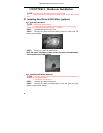
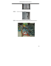
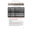
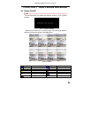
Fig 2.8 Rear Panel of 16-channel DVR
Item Name Description
1 VIDEO OUT Connect to monitor
2 SPOT OUT
Connect to monitor as an AUX output channel for
one channel. only displays video, not menu
3 VIDEO IN 16 Video inputs for cameras
4 AUDIO OUT Audio output, connect to speakers
5 AUDIO IN 4-channels audio input
6 S-VIDEO S-Video output, connect to monitor
7 PS/2 port Connect PS/2 mouse
8 USB port Only for USB mouse
9 RJ45 port Connect to internet
10 VGA port VGA output, connect to monitor
11 COM port For debugging
12 ALARM IN Connect to external sensor1-16.
13 +5V and GND +5 Voltage and Ground
14 ALARM OUT/PTZ
Relay output1-4. Connect to external alarm. PTZ
input
15 RS485 Connected to speed domes
16 FAN For cooling the device
17 POWER INPUT DC 12V
Tab2.4 Ports on Rear Panel of 16 channel
Note: The resolution of VGA output is 800*600/60Hz. If connected through VGA port,
please assure your display supports this display mode. (Most LCD screens can
adapt to it automatically without manual adjustment)
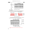
2.3.2 Installing Sensor & Alarm (optional)
The DVR has 16 channel alarm input and 4 channel alarm output.
Alarm Input:
The alarm input is triggered by electric level (High: 5V, Low: 0V). Users
can connect external sensors, like gas detectors, smoke detectors and
infrared detectors. Once the DVR detects that the electric level meets the
user’s settings it will trigger the DVR recording or alarm out.
For example, a sensor is connected to alarm input1 as Fig 2.1. Cable A
and B will be connected once the sensor detects an event. Users set
Device type as NC (Normal Close), refer to Fig 2.1. It will input +5V (high
level) to input1 when triggered, DVR will start recording.