


Installation instructions
5
DX-TVM111
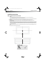
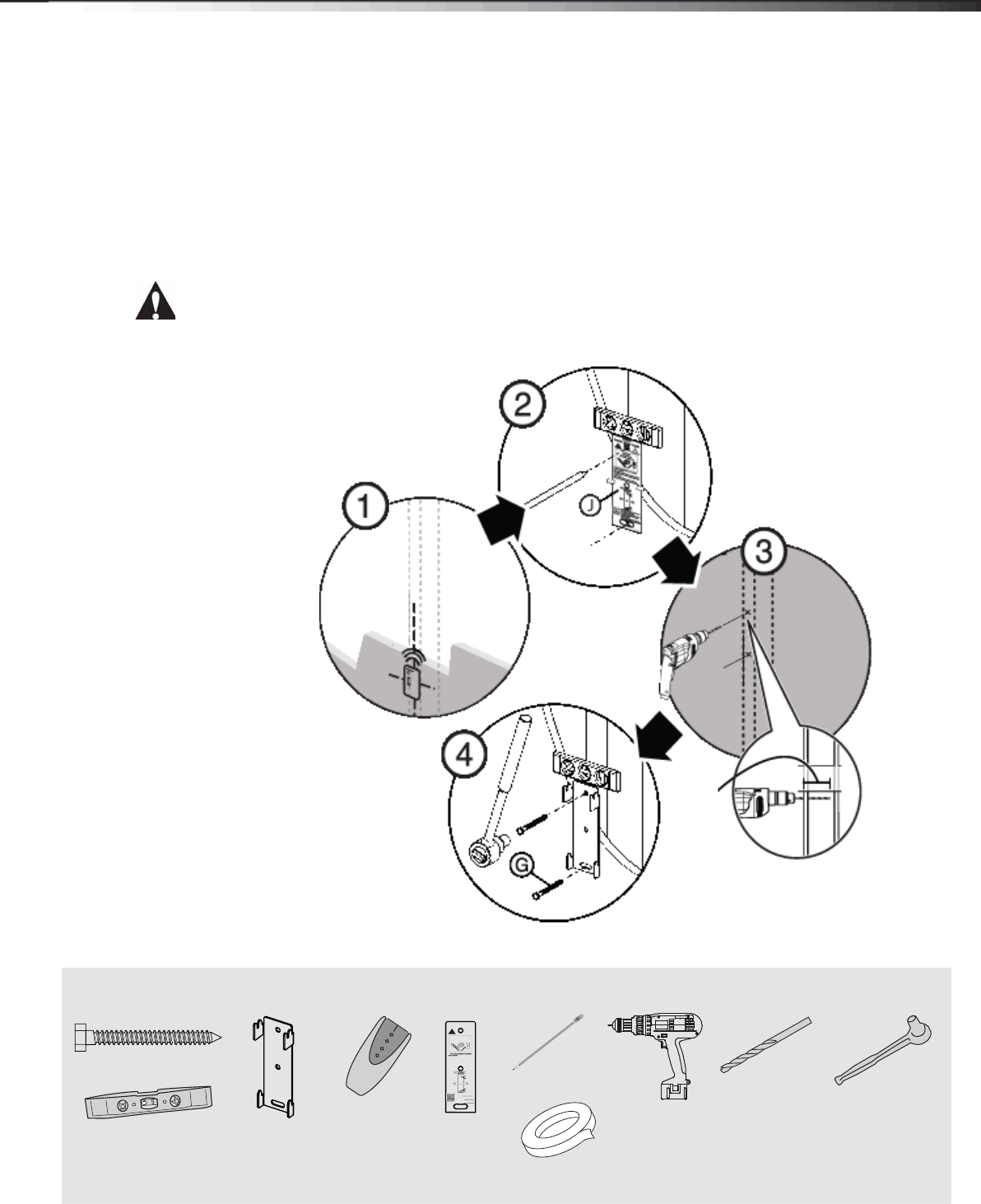
STEP 2 - Option 1: Installing on a wood stud* wall
Note: Any wallboard or material covering the wall must not exceed 5/8" (16 mm).
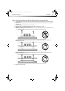
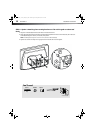
1 Locate the stud. Verify the center of the stud with an edge-to-edge stud finder.
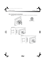
2 Align the wall plate template (J) at the height you determined in the previous step and make sure that it is
level. Tape the wall plate template in position, then use a pencil to mark the lag bolt hole locations (2).
Remove the wall plate template.
3 Drill pilot holes to a depth of 3 in. (75 mm) using a 1/8" (3 mm) wood drill bit.
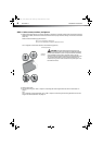
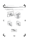
4 Align the wall plate (B) with the pilot holes, insert the lag bolts (G) through the holes in the wall plate, then
tighten the lag bolts only until they are firm against the arm assembly.
CAUTION: Avoid potential injuries or property damage!
DO NOT over-tighten the lag bolts (G).
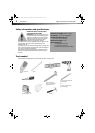
You’ll need
3 in.
(75 mm)
* Minimum wood stud size: common 2 x 4 in. (51 x 102 mm)
nominal 11/2 x 31/2 in. (38 x 89 mm).
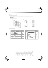
Top
Haut
Parte superior
DX-TVM111
Template • Gabarit • Plantilla
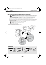
Tools Needed
Outils nécessaires
Herramientas requeridas
Note
Remarque : Pour une construction à ossature de bois,
localiser d'abord les montants en bois, à l'aide d'un
détecteur de montants.
Nota: para la instalación en construcciones de armazón de
madera, primero debe localizar las vigas de madera con un
localizador de vigas.
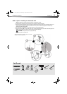
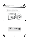
Need more information about your mount? Scan
this QR code or visit www.dynexproducts.com.
<FR>Need more information about your mount?
Scan this QR code or visit www.dynexproducts.com.
<SP>Need more information about your mount?
Scan this QR code or visit www.dynexproducts.com.
http://san.us/284
V1 13-0138
Edge-to edge
stud finder
G (2)
Pencil
Drill
1/8" wood
drill bit
7/16" socket
wrench
Level
Wall plate (B)
Template (J)
Tape
DX-TVM111_12-1055_MAN_V1_ENG - GIF.fm Page 5 Friday, March 22, 2013 4:12 PM