


1-6
2-Gigabit Disk-Array Enclosure (DAE2) Hardware Reference
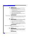
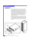
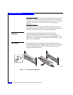
About DAE2 Disk Enclosures
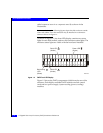
The enclosure address is set on the switch at installation. Disk module IDs are
numbered left to right (looking at the front of the unit) and are contiguous
throughout an array: enclosure 0 contains modules 0-14; enclosure 1 contains
modules 15-29; enclosure 2 includes 30-44, and so on through eight
enclosures.
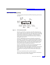
The enclosure EA switch and loop indicator are described in the
installation procedure in Chapter 2. The status lights are described in
the Monitoring Disk Enclosure Status section of Chapter 3.
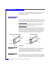
Midplane
A midplane between the disk modules and the LCC and
power/cooling modules distributes power and signals to all
components in the enclosure. LCCs, power/cooling modules, and
disk drives — the enclosure’s field-replaceable units (FRUs) — plug
directly into the midplane.
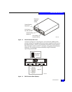
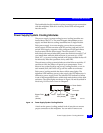
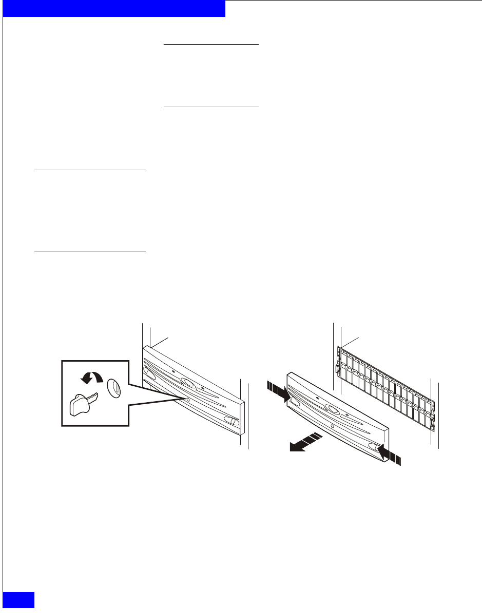
Front Bezel
The front bezel, shown in Figure 1-5, has a locking latch and an
electromagnetic interference (EMI) shield. You must remove the bezel
to remove and install drive modules. EMI compliance requires a
properly installed front bezel.
Figure 1-5 Disk Enclosure Front Bezel
EMC2173