


Link Control Cards (LCCs)
1-7
About DAE2 Disk Enclosures
Link Control Cards (LCCs)
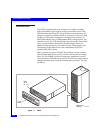
An LCC supports and controls one Fibre Channel loop and monitors
the DAE2.
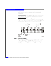
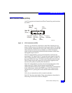
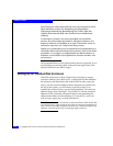
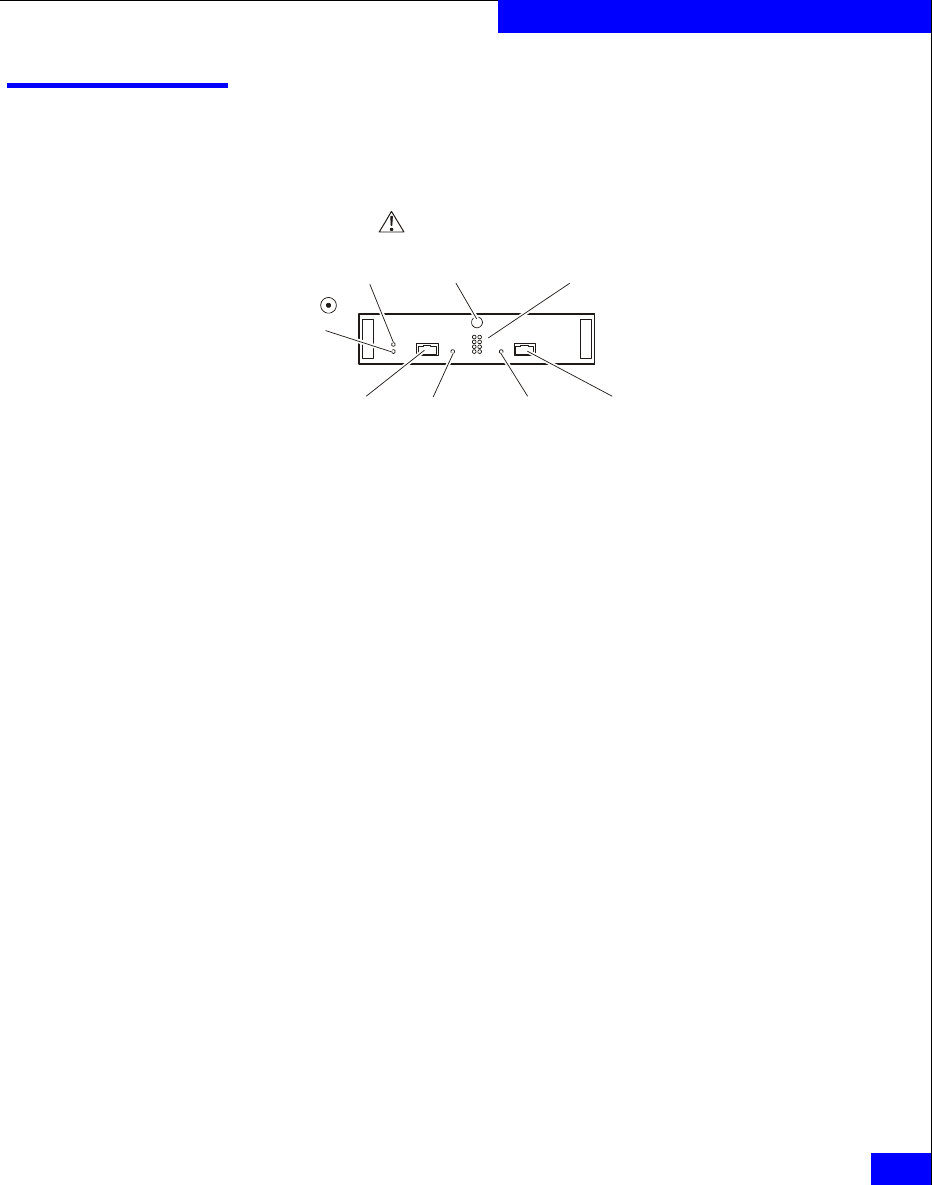
Figure 1-6 LCC Connectors and LEDs
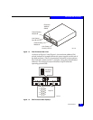
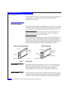
The LCCs in a DAE2 are connected to other Fibre Channel devices
(hosts, DAE2s, and so on) using twin-axial copper cables. The cabling
is not explicitly configured as a loop (with a long return from the last
disk enclosure to the server), but instead, as a set of full-duplex,
point-to-point connections with the last disk enclosure in the chain
closing the loop on its LCC.
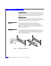
The LCC independently receives and electrically terminates the
incoming FC-AL signal. The LCC passes the input signal to the disk
drives in the enclosure; it then sends the output signal, via cables, to
the next DAE2 in the loop. ATA link control cards provide the same
Fibre Channel input and output, but convert those signals to and
from the ATA protocol used by their disk drives.
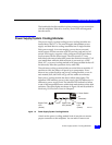
Each LCC independently monitors the environmental status of the
entire enclosure, using a microcomputer-controlled FRU
(field-replaceable unit) monitor program. The monitor communicates
status to the server, which polls DAE2 status. LCC firmware also
controls the LCC port bypass circuits and the disk-module status
lights.
LCCs do not communicate with or control each other.
Each LCC has four status lights. These status lights are described in
Monitoring Disk Enclosure Status in Chapter 3.
EMC2165
Power
LED
(Green)
Expansion
Link Active
LED
(
Green
)
Primary
Link Active
LED
(
Green
)
Expansion
Connector
Primary
Connector
Loop
ID LEDsLatch
Fault
LED
(Amber)