


Powerup and Initialization
2-11
Installing a DAE2
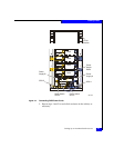
6. For proper cooling and normal operation, make sure all the disk
module slots in each disk enclosure contain either disk or filler
modules.
Do not power up a disk enclosure without at least one LCC installed.
You can configure a driveless disk enclosure within a Fibre Channel loop.
High availability with write-caching requires disks in slots 0-4 in the first
DPE2 or DAE2 connected to a storage processor (Enclosure Address 0,
loop 0).
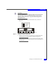
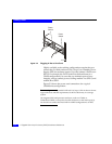
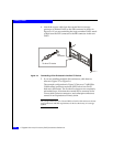
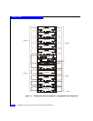
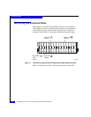
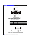
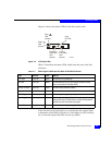
7. Turn the DAE2 power switch(es) to the on position. If necessary,
set the SPS switches, and then the main circuit breaker switches,
to the on position. The disk enclosures in the cabinet power up.
Powerup and Initialization
The only power switches on a DAE2 are those on the power
supply/system cooling module, which are normally on. As a result, a
DAE2 is always active.
When you initially apply ac power to a disk enclosure, the disk drive
modules power up according to their specifications, and spin up in a
specified sequence dictated by enclosure and loop IDs. The slot
spin-up delays range from 0 to 84 seconds. The same delays are used
when you insert a drive module while the system is powered up.
The LCC hardware monitor (FRU monitor) resets and begins its
control loop. The port bypass circuits enter the states indicated by
their associated drives. The monitor continues to run in this local
mode until it receives commands that dictate otherwise. In local
mode, the monitor maintains the port bypass circuits in the same
states as the drive command signals. When a drive fault occurs, the
corresponding drive fault light turns on. Firmware commands can
take control of the port bypass circuits and the drive status lights.
CAUTION
!
The drives read their FC-AL physical address only at powerup or
when the drive is reset. To avoid potential data loss, you must set
the enclosure address when you install the disk enclosure and
power is off; you cannot change the EA while power is on.