


4-1 L2401DC
CABINET DISASSEMBLY INSTRUCTIONS
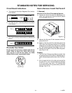
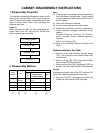
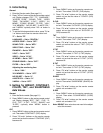
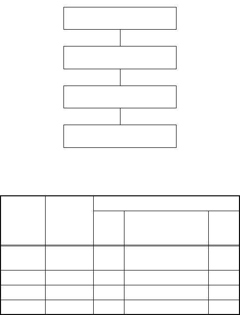
1. Disassembly Flowchart
This flowchart indicates the disassembly steps for the
cabinet parts, and the CBA in order to gain access to
item(s) to be serviced. When reassembling, follow the
steps in reverse order. Bend, route and dress the
cables as they were.
Caution !
When removing the CRT, be sure to discharge the
Anode Lead of the CRT with the CRT Ground Wire
before removing the Anode Cap.
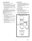
2. Disassembly Method
↓↓↓↓↓
(1) (2) (3) (4) (5)
Note :
(1) Order of steps in procedure. When reassembling,
follow the steps in reverse order. These numbers
are also used as the Identification (location) No. of
parts in figures.
(2) Parts to be removed or installed.
(3) Fig. No. showing procedure of part location
(4) Identification of part to be removed, unhooked, un-
locked, released, unplugged, unclamped, or des-
oldered.
S=Screw, P=Spring, L=Locking Tab, CN=Con-
nector, *=Unhook, Unlock, Release, Unplug, or
Desolder
2(S-2) = two Screws (S-2)
(5) Refer to the following "Reference Notes in the
Table."
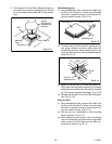
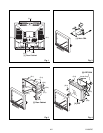
Reference Notes in the Table
1. Removal of the Rear Cabinet. Remove screws
7(S-1), 2(S-2) and (S-4) then slide the Rear Cabi-
net backward.
2. Removal of the CRT CBA. Disconnect CN1501
then pull the CRT CBA backward.
3. Removal of the Main CBA. Disconnect CN571 on
the Main CBA then slide the Main CBA backward.
Caution:
Discharge the Anode Lead of the CRT with the CRT
Ground Wire before removing the Anode Cap.
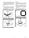
4. Removal of the CRT. Remove screws 4(S-3) and
Anode Cap. then slide the CRT backward.
Step/
Loc. No.
Part
Removal
Fig.
No
Remove/*unlock/
release/unplug/
unclamp/desolder
Note
[1]
Rear
Cabinet
1,2
7(S-1), 2(S-2),
(S-4)
1
[2] CRT CBA 4,5 CN501 2
[3] Main CBA 3,5 CN571 3
[4] CRT 4 4(S-3), Anode Cap 4
[1] Rear Cabinet
[2] CRT CBA
[3] Main CBA
[4] CRT