


5-1 L2401EA
ELECTRICAL ADJUSTMENT INSTRUCTIONS
General Note:
"CBA" is abbreviation for "Circuit Board Assem-
bly."
NOTE:
Electrical adjustments are required after replacing
circuit components and certain mechanical parts.
It is important to perform these adjustments only
after all repairs and replacements have been com-
pleted.
Also, do not attempt these adjustments unless the
proper equipment is available.
Test Equipment Required
1. NTSC Pattern Generator (Color Bar W/White
Window, Red Color, Dot Pattern, Gray Scale,
Monoscope, Multi-Burst)
2. DC Voltmeter
3. Oscilloscope: Dual-trace with 10:1 probe,
V-Range:0.001~50V/Div,
F-Range: DC~AC-60MHz
4. Plastic Tip Driver
5. Remote control unit: Part No. NE122UD
6. DC power supply 13.2V/5A
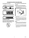
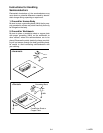
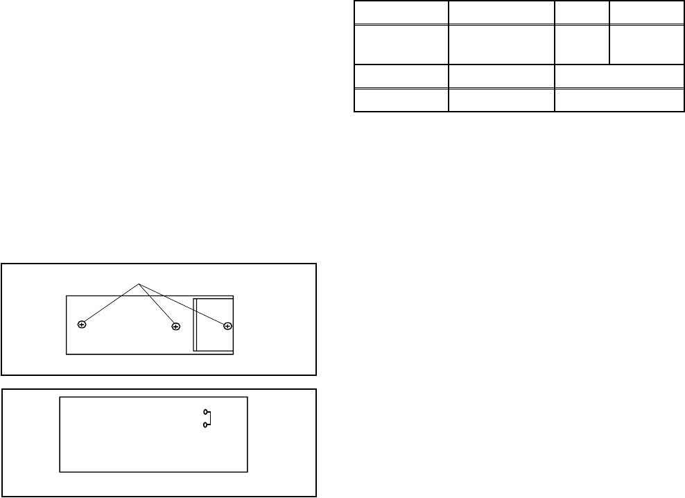
How to make Service remote control unit:
1.
Prepare normal remote control unit.
(Part No. NE122UD --- [ 6420FE ])
(Part No. NE154UD, NE142UD, N0108UD,
N0132UD, NE116UD, NE153UD, NE141UD,
NE122UD, or NE121UD --- [ EWF2004 ])
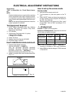
Remove 3 Screws from the back lid. (Fig. 1-1)
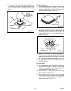
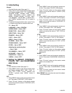
2. Added J1 (Jumper Wire) to the remote control CBA.
(Fig. 1-2)
How to set up the service mode:
Service mode:
1. Use the service remote control unit.
2. Turn the power on. (Use main power on the TV
unit.)
3. Press "SLEEP" button on the service remote con-
trol unit. Version of micro computer will display on
the CRT. (Ex: 058-0.06)
4. Check the display on the lower left is "2641" and if
it is not "2641," set it at "2641" according to "2. Ini-
tial Setting."
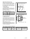
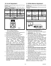
1. +B Adjustment
Purpose: To obtain correct operation.
Symptom of Misadjustment: The picture is dark and
the unit does not operate correctly.
Note: TP601, TP300(GND), VR661 --- Main CBA
1. Connect DC Volt Meter to TP601 and TP300(GND).
2. Adjust VR661 so that the voltage of TP601 becomes
+114±0.5V DC.
SCREWS
REMOTE CONTROL UNIT
Fig. 1-1
J 1
Fig. 1-2
REMOTE CONTROL CBA
Test Point Adj. Point Mode Input
TP601(+B)
TP300(GND)
VR661 --- ---
Tape M. EQ. Spec.
--- DC Voltmeter +114±0.5V DC.