


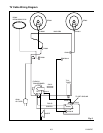
2-4 L6115IMP
Safety Check after Servicing
Examine the area surrounding the repaired location
for damage or deterioration. Observe that screws,
parts and wires have been returned to original posi-
tions. Afterwards, perform the following tests and con-
firm the specified values in order to verify compliance
with safety standards.
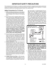
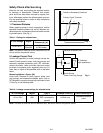
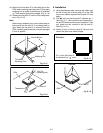
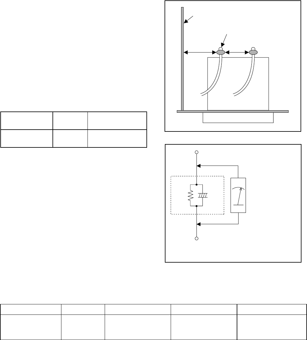
1. Clearance Distance
When replacing primary circuit components, confirm
specified clearance distance (d) and (d') between sol-
dered terminals, and between terminals and surround-
ing metallic parts. (See Fig. 1)
Table 1 : Ratings for selected area
Note: This table is unofficial and for reference only. Be
sure to confirm the precise values.
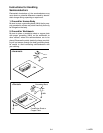
2. Leakage Current Test
Confirm the specified (or lower) leakage current be-
tween B (earth ground, power cord plug prongs) and
externally exposed accessible parts (RF terminals,
antenna terminals, video and audio input and output
terminals, microphone jacks, earphone jacks, etc.) is
lower than or equal to the specified value in the table
below.
Measuring Method : (Power ON)
Insert load Z between B (earth ground, power cord
plug prongs) and exposed accessible parts. Use an
AC voltmeter to measure across both terminals of load
Z. See Fig. 2 and following table.
Table 2 : Leakage current ratings for selected areas
Note: This table is unofficial and for reference only. Be sure to confirm the precise values.
AC Line Voltage Region
Clearance
Distance (d), (d')
110 to 130 V
USA or
CANADA
≥ 3.2 mm
(0.126 inches)
Chassis or Secondary Conductor
dd'
Primary Circuit Terminals
Fig. 1
AC Voltmeter
(High Impedance)
Exposed Accessible Part
B
Earth Ground
Power Cord Plug Prongs
Z
1.5kΩ
0.15µF
Fig. 2
AC Line Voltage Region Load Z Leakage Current (i) Earth Ground (B) to:
110 to 130 V USA
0.15µF CAP. & 1.5kΩ
RES. connected in
parallel
i≤0.5mA rms
Exposed accessible
parts