


5-5 L2401EA
12. Cut-off Adjustment
Purpose: To adjust the beam current of R, G, B, and
screen voltage.
Symptom of Misadjustment: White color may be
reddish, greenish or bluish.
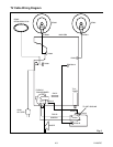
Note: Screen Control FBT --- Main CBA
F.B.T= Fly Back Transformer
Use service remote control unit
1. Degauss the CRT and allow CRT to operate for 20
minutes before starting the alignment.
2. Input the Black Raster Signal from RF Input.
3. Enter the Service mode. (See page 5-1)
4. Press "VOL p" button on the service remote con-
trol unit and select "C/D" mode. (Display changes
"C/D," "7F," "LANGUAGE," "ACCESS CODE,"
"SOUND TYPE," "VIDEO TONE," "FM MODE,"
"V-OUT," "VIDEO," "AV MEMO," "STABLE
SOUND," "FILTER," "1000," "YUV MEMORY,"
"NO SIG BRT," "A-MUTE POL," and "V-MENU"
cyclically when "VOL p button is pressed.) then
press "1." The display will momentarily show "CUT
OFF R" (R= Red). Now there should be a horizon-
tal line across the center of the picture tube. If
needed gradually turn the screen control on the fly-
back, clockwise until the horizontal line appears.
Adjust the Red Cut off by pressing the "CH o/p"
buttons. Proceed to Step 5 when the Red Cut off
adjustment is done.
5. Press the "2" button. The display will momentarily
show "CUT OFF G" (G=Green). Adjust the Green
Cut off by pressing the "CH o/p" buttons. Proceed
to step 6 when the Green Cut off adjustment is done.
6. Press the "3" button. The display will momentarily
show "CUT OFF B" (B=Blue). Adjust the Blue cut
off by pressing the "CH o/p" buttons. When done
with steps 4, 5 and 6 the horizontal line should be
pure white if not, then attempt the Cut off adjust-
ment again.
13. White Balance Adjustment
Purpose: To mix red, green and blue beams correctly
for pure white.
Symptom of Misadjustment: White becomes bluish
or reddish.
Note: Use service remote control unit
1. Operate the unit more than 20 minutes.
2. Face the unit to east. Degauss the CRT using De-
gaussing Coil.
3. Input the White Raster (APL 100%).
4. Set the color analyzer to the CHROMA mode and
after zero point calibration, bring the optical recep-
tor to the center on the tube surface (CRT).
5. Enter the Service mode. Press "VOL p " button on the
service remote control unit and select "C/D" mode.
(Display changes "C/D," "7F," "LANGUAGE," "AC-
CESS CODE," "SOUND TYPE," "VIDEO TONE,"
"FM MODE," "V-OUT," "VIDEO," "AV MEMO,"
"STABLE SOUND," "FILTER," "1000," "YUV
MEMORY," "NO SIG BRT," "A-MUTE POL," and
"V-MENU" cyclically when "VOL p" button is
pressed.) then Press No. 8 button on the service re-
mote control Unit.
6. Press No. 4 button on the service remote control
unit for Red adjustment. Press N0. 5 button on the
service remote control unit for Blue adjustment.
7. In each color mode, Press "CH o/p " button to adjust
the values of color.
8. Adjusting Red and Blue color so that the temperature
becomes 9200K (x: 286 / y: 294)±3%.
9. At this time, Re-check that Horizontal line is white.
If not, Re-adjust Cut-off Adjustment until the Hori-
zontal Line becomes pure white.
10. Turn off and on again to return to normal mode. Re-
ceive APL 100% white signal and Check Chroma
temperatures become 9200K (x: 286 / y: 294)±3%.
Note: Confirm that Cut Off Adj. is correct after this
adjustment, and attempt Cut Off Adj. if needed.
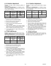
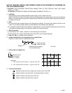
Test Point Adj. Point Mode Input
---
Screen-Control
CH o / p
buttons
RF
Black
Raster
Tape M. EQ. Spec.
---
Pattern
Generator
See Reference
Notes below.
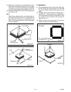
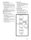
Figure
PATTERN GENERATOR
Fig. 2
EXT. INPUT
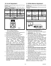
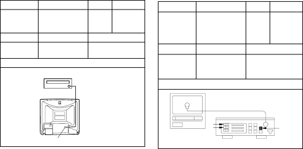
Test Point Adj. Point Mode Input
Screen
CH o / p
buttons
RF
White
Raster
(APL
100%)
Tape M. EQ. Spec.
---
Pattern
Generator,
Color analyzer
See below
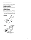
Figure
Color Analyzer
Fig. 3