


M1
M2
M3
M4
N1
N2
N3
N4
O1
O2
O3
O4
P1
P2
P3
P4
Q1
Q2
Q3
Q4
R1
R2
R3
R4
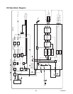
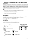
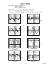
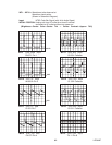
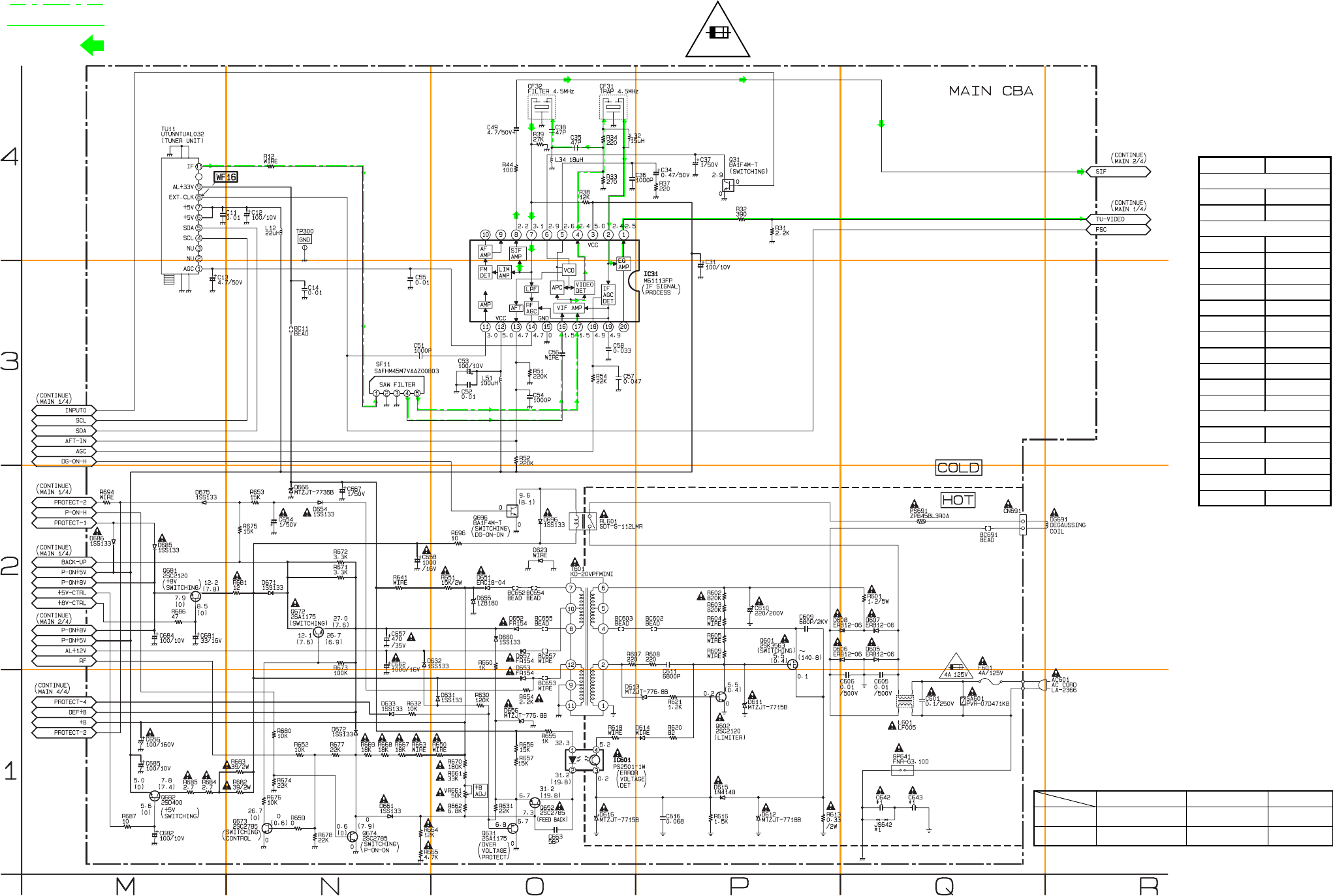
IF SIGNAL
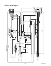
VIDEO SIGNAL
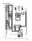
AUDIO SIGNAL
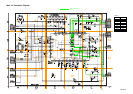
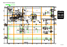
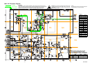
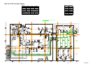
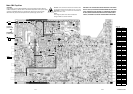
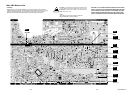
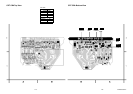
Main 3/4 Schematic Diagram
L2401SCM3
7-7
7-8
NOTE :
The voltage for parts in hot circuit is measured
using hot GND as a common terminal.
CAUTION: FOR CONTINUED PROTECTION AGAINST RISK
OF FIRE, REPLACE ONLY WITH SAME TYPE 4A, 125V FUSE.
ATTENTION: UTILISER UN FUSIBLE DE RECHANGE DE
MÊME TYPE DE 4A, 125V.
4A/125V
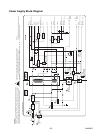
CAUTION !
Fixed voltage ( or Auto voltage selectable ) power supply circuit is used in this unit.
If Main Fuse (F601) is blown, check to see that all components in the power supply
circuit are not defective before you connect the AC plug to the AC power supply.
Otherwise it may cause some components in the power supply circuit to fail.
*
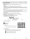
1 NOTE:
The Capacitor ( C643 ) is either type A or type B.
These two types are exchangeable and can be
equally used whichever the model is . The difference
between type A and type B is shown in the table below.
Type A
Type B
4700P/250V
0.01/250V
0.01/250V
Not Used
C643 C642 JS642
Not Used
WIRE
MAIN 3/4
Ref No. Position
IC31
P-3
IC601
O-1
Q31
P-4
Q601
P-2
Q602 P-1
Q631 O-1
Q652 O-1
Q672 N-2
Q673 N-1
Q674
N-1
Q681 M-2
Q682 M-1
Q696
O-2
CN691
Q-2
TP300
N-4
VR661 O-1
ICS
CONNECTOR
VARIABLE RESISTOR
TEST POINT
TRANSISTORS