


Two cables are required per sensor. The RG178 should be
used where the cable itself is subject to temperatures
exceeding 74°C.
2. Control Unit Installation
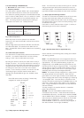
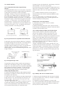
All cable connections are made to the terminal blocks along
the bottom edge of the pcb (see fig.5). Release the terminal
screw before inserting the wire.
2.2 External Connections
Protection for permanently installed equipment
NOTE: This equipment is regarded as permanently installed
equipment and must be wired up using suitable cable for the
current and voltage specified. A suitable switch or circuit
breaker must be included in the installation and this should be
in close proximity to the equipment and marked as its
disconnecting device. A suitable fuse rated at 3A must be fitted
in the supply. Each relay circuit must be protected by a fuse not
exceeding the maximum rated current for the relay as specified
in the manual.
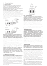
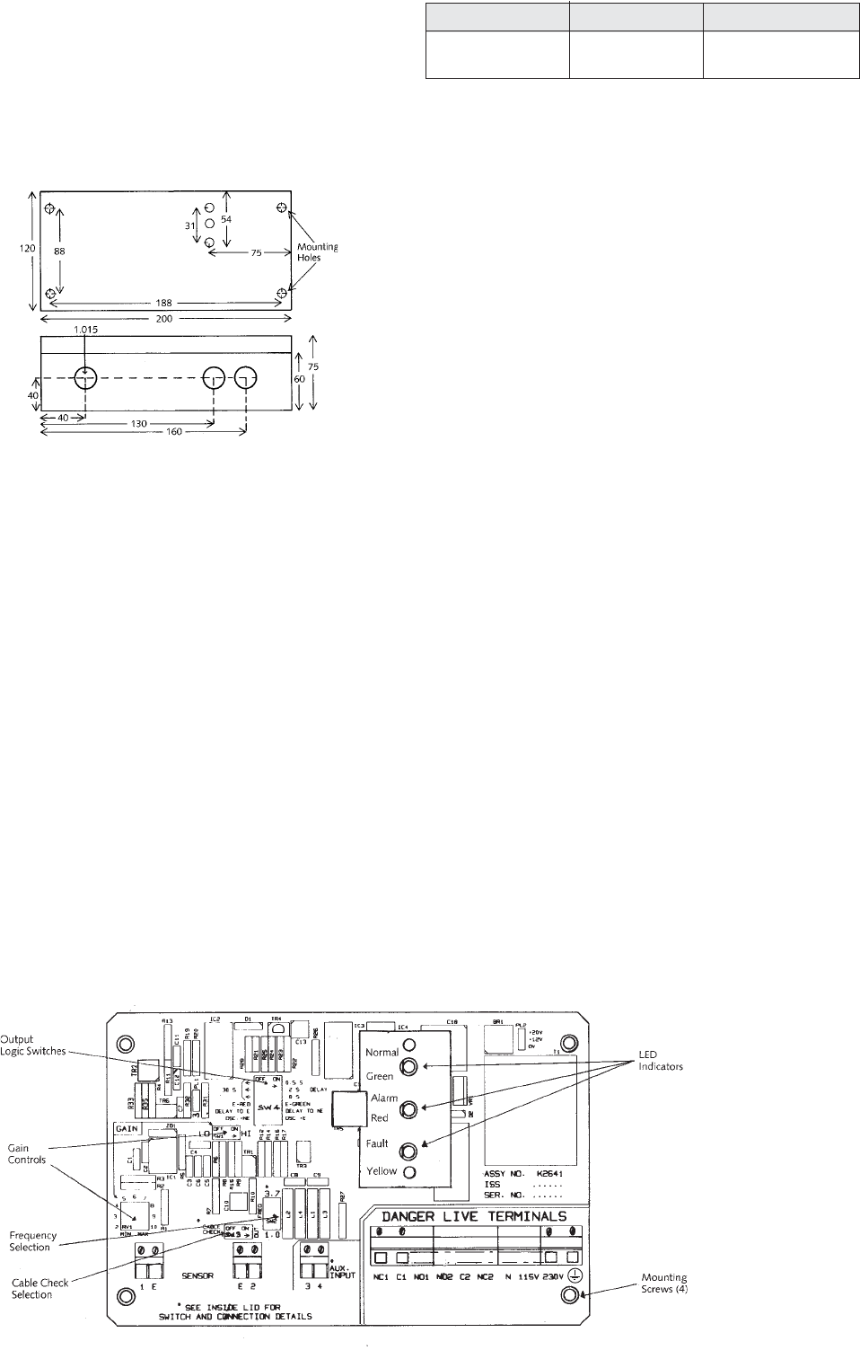
Fig. 4 MCU200 housing dimensions
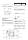
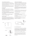
50mtr 50-100m over 100m
RG174 URM76 Consult
RG178 RG58 factory
Fig 3 Suitable extension cables
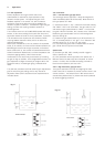
2.1 Mechanical
The control unit is supplied with three holes drilled in the
bottom (longer) side of the box. Two glands are supplied for
the power input cable and relay output cable. The sensor is
normally supplied fitted with a suitable gland on the cable.
Two further holes can be drilled in the bottom side of the box
should these be needed: it is recommended that the circuit
board is removed whilst drilling extra gland holes.
(i) AC Mains is connected between the “N” terminal for
neutral and one of the “115V” or “230V” terminals
depending on the voltage supply available - BEWARE - the
terminal not connected externally will be “live” once the
transformer is powered via the other terminals.
(ii) Protective earth
NOTE: A protective earth should be used for all applications
(iii) The DPCO relay has two sets of contacts. These are
labelled:
Set 1: NC1 - Normally closed
C1 - Common
NO1 - Normally open
Set 2: NC2 - Normally closed
C2 - Common
NO2 - Normally open
Relay warning
CAUTION: External circuits (such as signal circuits) with
accessible parts or basic insulation only, MUST NOT be
connected to the relay if the relay is also connected to external
circuits which are hazardous live (mains circuits).
(iv) The Sensor connections are labelled “1”, “E” for the
receiver crystal and “2”, “E” for the coax cable to the
transmitter crystal. The screens of these coax cables are
connected to the terminals marked “E”.
(v) The Auxiliary Input is a terminal which can be connected
to a “push to reset” button to achieve a latching alarm, or to
another Mobrey control unit, to give a pump control from the
MCU200 unit relay output. If a short circuit is connected
between terminals 3 & 4, the MCU200 relay, once de-
energised, is held de-energised. Even if the sensor attached
to the MCU200 changes state, to that which should energise
the output relay, this relay will not energise until the link
between terminals 3 & 4 is broken in the circuit external to
the MCU200. See section 3.3.
Fig. 5
MCU201 PC Board