


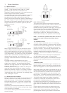
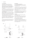
3.3 Pump control and latching alarms
The output relay of the MCU200 can be latched into the de-
energised state. This latch is achieved by short circuiting the
two terminals of the Auxiliary input, labelled as terminals 3 &
4 on the pc board (see figure 5). The relay will remain de-
energised while the latching short circuit is applied. Only
after this circuit is broken can the relay re-energise under the
control of the sensor.
A latching alarm can therefore be achieved by connecting one
pole of the output relay into the auxiliary input, through a
push to break “reset” button. NC1 and C1 should be used to
create this latch, with NC2, C2 and NO2 being used for the
external alarm circuit.
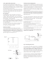
For a pump control application, switching a pump to control a
liquid between two sensors in a tank, this auxiliary input can
be used to monitor the second sensor. The control system
must be designed as follows:
(i) The pump to be latched “on” must be driven by the
MCU200 output relay.
(ii) The sensor attached directly to the MCU200 must
initiate the pump action to be latched.
(iii) The latched pump action occurs when the MCU200 relay
is de-energised.
(iv) The separate sensor must be used to detect the liquid
presence at the switch off point.
(v) The signal from the separate sensor to switch off the
pump must be an open circuit, and is connected to the
auxiliary input in the MCU200.
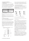
3.2.3. High level alarm, Hisens sensor
The Hi-Sens sensor oscillates when the sensor is dry, so
producing a fail safe high level alarm. Normally such systems
have the relay de-energising for alarm. This example has time
delay of 30 seconds to Normal to allow the operator to identify
any tank giving an occasional alarm.
Note that all Hisens sensors are 1 MHz and that cable check
circuit is out - firstly because it does not function with Hisens
but secondly that a cable fault with Hisens will produce an
alarm signal anyway.
Gain adjustment:
(i) With sensor dry, reduce time delays to 2 seconds for
simpler adjustment. Set gain switch to “LO” and reduce pot
to “MIN”. Red LED will illuminate - this is the “false wet”.
Rotate the gain potentiometer clockwise slowly until the green
LED illuminates: note the setting (X).
(ii) Increase the gain setting X + 3 if it is necessary to switch
to the “HI” gain range, re-check for a “false wet” position on
the “HI” range, or assume an overlap between “LO” and “HI”
of 2 divisions of gain.
(iii) Check that the sensor when immersed in water gives an
alarm output. Recheck in the liquid to be monitored.
(iv) Reset the time delays as needed.
Special site conditions:
In the above application the time delay can be used to
prevent high level alarms caused by splashing of the sensor, by
setting the green switch to “Delay to NE”. Avoiding severe
splashing or condensation effects may require a slight increase
in the gain setting to X + 4. To detect splashing or for use on
light oils the gain can be reduced to X + 2.
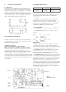
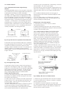
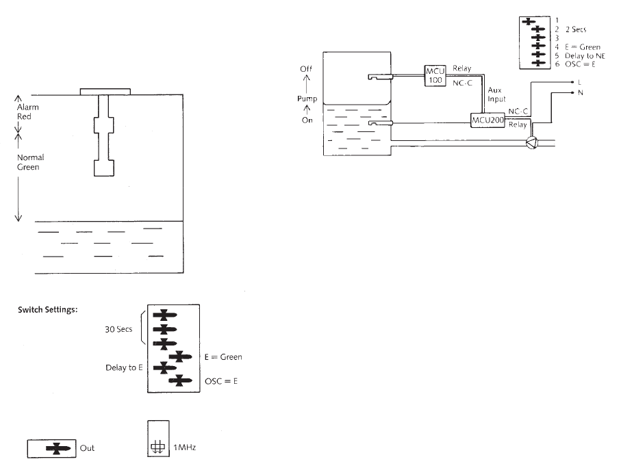
Fig. 12 Tank filling pump control
In this example the number 6 switch (blue) on the MCU200
would be set to OSC = E, so that when the lower gap sensor
sees air it de-energises the relay to bring on the pump. With
switch number 4 (yellow) set to E = GREEN, the red LED
illuminates when the pump is running. With “Delay to NE”
set at 2 seconds, the sensor will ignore occasional bubbles or
surface turbulence which could trigger a pump start.
The high level sensor, illustrated as a Mobrey MCU200 plus
sensor, could alternatively be a Mobrey 005, or another
MCU200 or a float operated level switch: all will give a volt
free contact output suitable for the auxiliary input on the
lower MCU200.
Fig. 11