


3.4 Interface Detection
3.4.1. Suspended Solids blanket sludge discharge
detection
The Mobrey MCU200 control unit can be used in conjunction
with a 433S sensor to provide sludge blanket level detection in
a settling tank, facilitating the control of automatic
desludging. Similarly, in conjunction with a Mobrey sludge
pipe using a pair of 488S sensors, the MCU200 can control
the end of desludge cycle when thin solids are discharged.
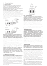
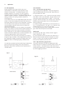
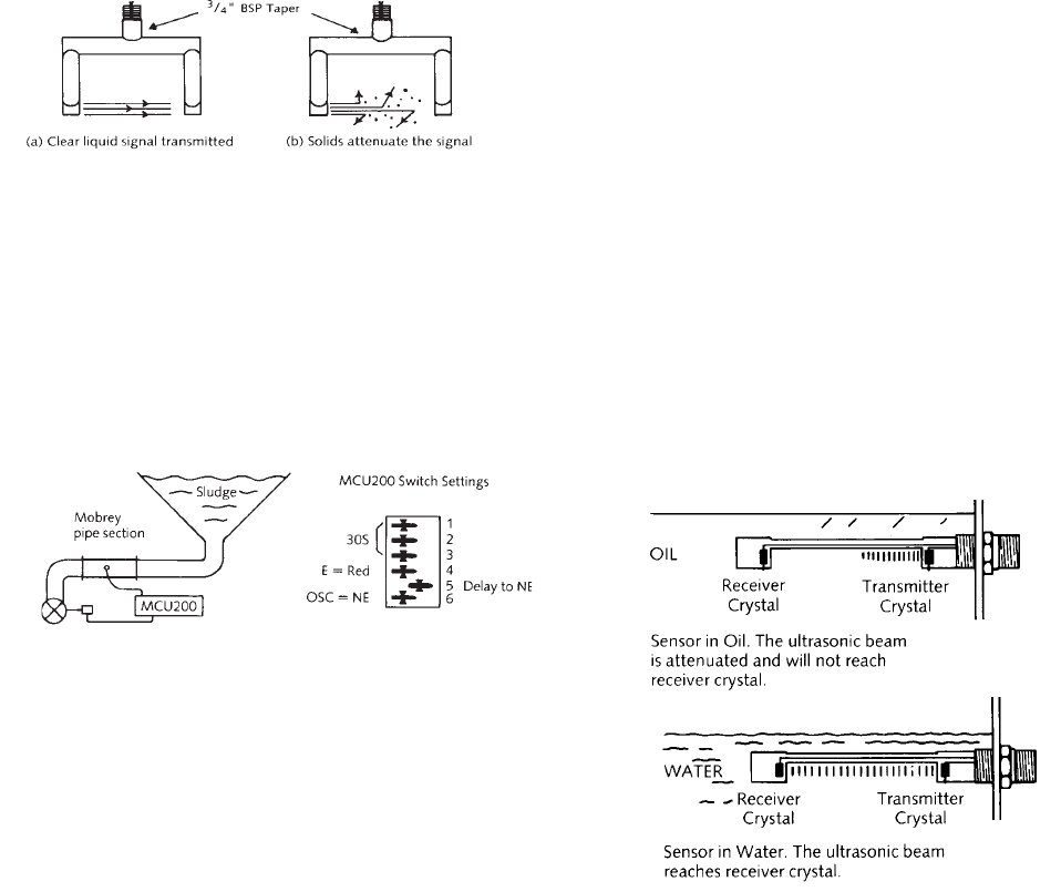
Figure 13 shows the operation of the sensor. In a clear liquid
the ultrasonic signal is carried across the gap and the sensor
“oscillates”. In a dirty liquid - one containing high levels of
suspended solids - the signal cannot cross the gap and the
oscillation ceases. (Note that this is the same condition that
occurs when the sensor is in air.) The Mobrey 433 sensor is
normally suspended in the settling tank itself.
Fig. 13 Type 433 sensor for suspended solids blanket alarm
An alternative sensor type is Mobrey sludge pipe, installed on
the sludge discharge line from the tank. In this application it
is essential to install the pipe section close to the tank
discharge, below the bottom of the tank. This maintains the
hydraulic pressure on the sludge to prevent release of
dissolved gases. Any such air entrained will give a false “thick
sludge” indication.
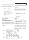
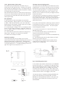
Fig. 14 Sludge discharge control
The application of fig 14 shows a control valve opening on a
timed basis to discharge the sludge. Once sludge is flowing
along the line, the control valve can be closed by the MCU200
when sludge of low density is detected. The gain pot gives
adjustment of the % solids level at which the output relay
trips, increasing sludge density for clockwise rotation.
Settled sludge discharge control
(i) Reduce time delays (see fig 8) to make adjustment easier.
Set frequence of operation to 1 MHz (see fig 5) if the sensor
will operate at this frequency.
(ii) With sensor or pipe in relatively clean water (supernatant)
set gain switch to “LO” and reduce gain pot (see fig 5) until
the LED changes. Note this point on the pot as the “zero
suspended solids” switch point.
(iii) For a 1 MHz sensor on a 150mm or 200mm ID pipeline
or sensor gap, working on primary sewage sludges, each
division on the potentiometer increase above this zero switch
point represents approximately 1% suspended solids.
Increase the pot to the desired level, remembering a 2 division
overlap between “LO” and HI” gain ranges.
Check the setting in practice by taking a sludge sample at the
switch point, and adjust as necessary. Increasing the gain pot
makes the switch point occur at a higher suspended solids
level.
(iv) For different diameter pipelines or sensor gaps, of
dimensions Dmm, each division represents (180¸D) % solids
approximately.
(v) In a 3.7 MHz system, on a 150mm gap sensor each
division represents 0.25% solids: for sensor gaps Dmm the
divisions are (38¸D) % solids typically.
Overflow alarm or fine solids detection
(i) Set frequency to 3.7 MHz if sensor is suitable.
This improves sensitivity.
(ii) Reduce time delays and locate “zero” position as above.
(iii) Assume gain pot adjustment is (90¸D) % solids per division
increase to set initial switch point.
3.4.2. Interface detection between two dissimilar liquids
Viscous liquids, emulsions and liquids containing solid
particles have a greater ultrasonic attenuation than clear
liquids. This technique is used to detect which liquid is
present at the sensor, for example for the separation of oil and
water. For this duty Mobrey 402 or 433 sensors are used,
operating at 3.7 MHz to produce the maximum ultrasonic
difference between two liquids monitored. An alternative
technique for pipelines is the use of a Mobrey sludge pipe
section with 448 type sensors.
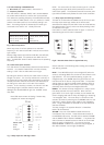
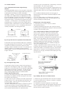
The gain is adjusted so that the sensor oscillates only in the
liquid with the lower ultrasonic attenuation: this is usually the
clearer liquid (water in the example of fig 15). Note that the
signal when oil is present in the sensor gap will be the same
as that for air in the gap, and that emulsion layers give a very
high attenuation.
Fig. 15 Mobrey 402 sensor as oil/water interface
(i) Reduce the gain potentiometer with the sensor immersed
in one of the liquids until a “false dry” indication is obtained.
Note the position of the pot.
(ii) Repeat for the sensor immersed in the other liquid
(iii) Set the potentiometer half way between these two values.
Correct performance requires a total difference between the
two set points of at least 3 divisions.