


3.1 Gain adjustment
Correct adjustment of the gain (HI/LO switch and
potentiometer) is essential for proper operation of any
ultrasonic sensor system. This adjusts the gain of the
feedback amplifier in the control unit, which produces
oscillation of the sensor when the coupling between the
ultrasonic crystals is sufficient. Therefore the higher the gain
setting, the lower the coupling needed to produce an
oscillating sensor.
The universal control unit of the MCU200 operates with many
sensors, so the correct setting for the particular sensor and
application should be found on site by experiment, if possible.
This will take account of particular site conditions like RF
coupling between extension cables, which can affect the
maximum allowed gain.
Other liquid characteristics, such as presence of suspended
solids, or air bubbles, can mean that for reliable operation the
MCU200 gain must be set as high as possible, to overcome
future solids build up, but at least one potentiometer division
below the maximum allowed level, to ensure temperature and
component ageing stability. With Hisens sensors,
condensation on the sensor may be overcome by increasing
the gain as high as possible. With sludge blanket sensors, the
gain adjustment changes the density of sludge at which the
system will switch, increased gain giving increased solids
levels.
The particular procedures outlined below for gain adjustments
give the mid point gain settings, which may need to be
adjusted to meet specific site/sensor future requirements as
indicated above.
3.2 Level Alarm
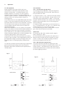
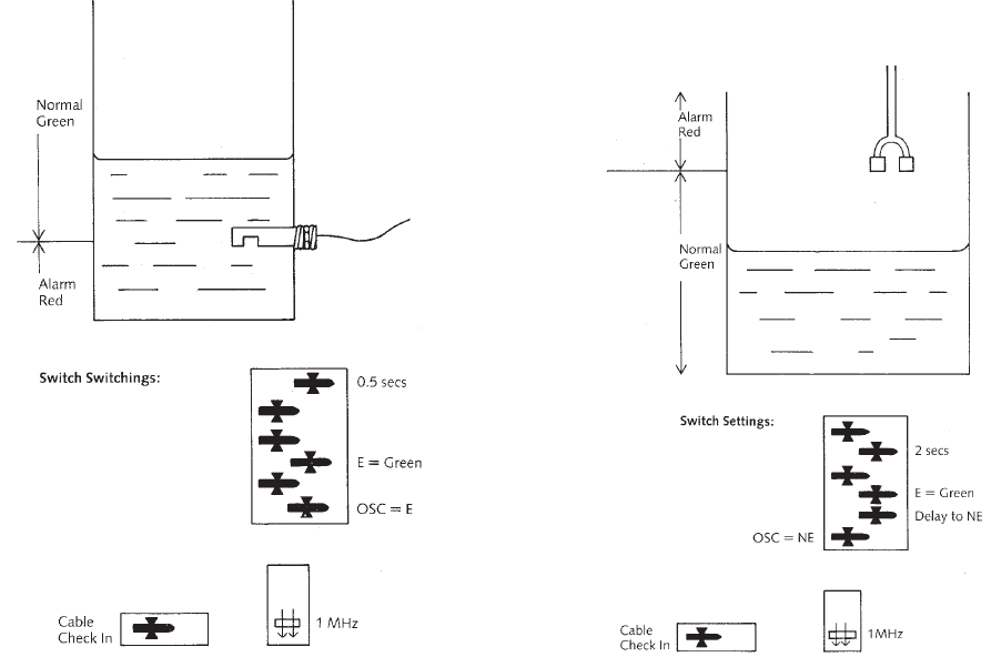
3.2.1. Low level alarm, gap type sensor
The normal gap sensor application. Relay de-energises for
alarm immediately (after 50 milliseconds). Most sensors of
this type operate at 1 MHz.
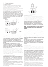
(i) Check that sensor is “dry”, cables are connected correctly
and “FAULT” LED is not illuminated. Put gain switch to “HI”
and rotate the gain potentiometer to “MAX”. In most cases
the green LED will illuminate, this is known as the “false wet”.
Rotate the gain potentiometer until this LED extinguishes.
Note the setting (X).
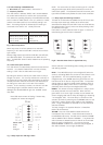
(ii) Reduce the gain potentiometer by 4 divisions from X, to
X-4. If necessary switch to “LO” gain. If no “false wet” was
possible set gain to “6” on the “HI” gain range.
(iii) Check that the green LED illuminates when the sensor
gap is filled with the liquid to be monitored.
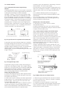
Special cases
(a) Sensors type 362, 366, normally used for cryogenic
duties, operate at 3.7 MHz.
(b) Non penetration sensors type 601, 621 operate at 3.7
MHz and have a low wet to dry ratio compared to normal
sensors. For 601, 621 the false wet setting X should be
found and the operation point set to X-1.
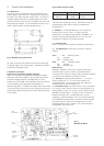
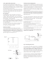
3.2.2. High level alarm, gap type sensor
This typical application has relay de-energising for alarm.
Cable check here is important to provide a sensor check in the
normal condition. The example uses 1 MHz sensors and 2
seconds delay before alarm, to prevent wave action produced
by stirrers triggering the alarm.
Fig. 9
Fig. 10
3. Applications