


2.3 Switch Settings in MCU200 Series
(i) Gain switch(and potentiometer): See section 3.
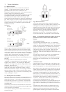
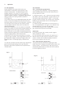
(ii) Frequency selection
This slide switch is labelled “FREQ” and is located between
the sensor terminal block E2, and the Aux input terminals.
This selects the operating frequency of the MCU200 oscillator,
which is either 3.7MHz (switch in the 'up' position) or 1 MHz,
(switch to the down position). The ex-factory setting is to 1
MHz. The setting required is dictated by the sensor type
connected to the control unit. Usually these are:
Where any sensor is built to operate at non standard
frequency, it will have the suffix M1 or M3 at the end of the
type number.
Mobrey sludge sensors type 433 and 448 with the suffix M1,
built after S/No 9001, can operate at both 1MHz and 3.7
MHz. The MCU201 selection switch determines the operating
frequency.
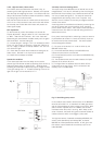
(iii) Cable check option selection
This slide switch is located directly above the sensor terminal
block E2. It is labelled “Cable Check” and the ex factory
setting is “OUT” with the slide switch to the right.
By sliding this switch to the left, the cable check circuitry is
brought into action. This circuitry monitors the continuity of
the screens of the two coaxial cables attached to the sensors:
normally these are linked at the sensor to the metal body of
the fitting (or to each other in the case of non metallic
sensors). If this continuity is broken, the “FAULT” LED will
illuminate giving an indication that the sensor cable is
damaged, and the MCU200 will give the “ALARM” output
relay state.
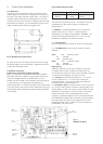
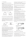
Fig. 7 Relay output and LED logic switch
Note: OSC means sensor oscillating, E means relay
energised, NE means de-energised
NOTE: The construction of Hisens sensors type HL* and HD*
and gap sensors types 601S, 621S prevents the use of this
cable check system. The separated nature of the sensor pairs
type 442S or 448S usually makes this cable check unreliable.
(iv) Relay output and LED logic selection
The bank of six slide switches towards the top of the pcb sets
the relay output state logic relative to the sensor state,
associated time delays and the LEDs. These are slide switches,
best adjusted with a pencil, and the ex factory wetting is with
all switches to the right.
Each switch is colour coded as shown in figure 7, and the pc
board labels give brief function information.
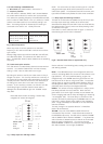
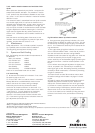
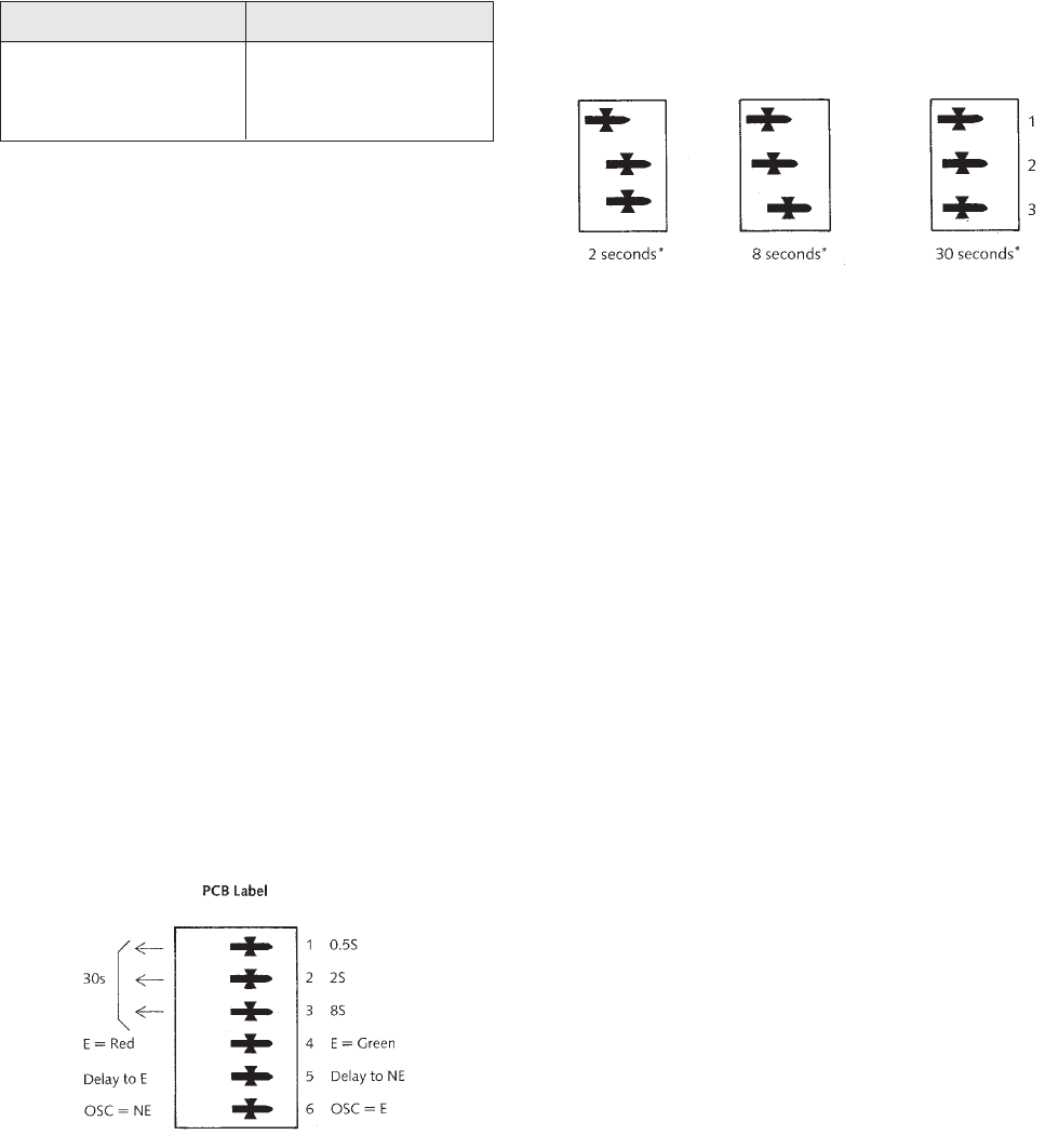
Fig 8 * Note that these times are approximate only
Set the switches in the following order, starting at the bottom
and working upwards.
BLUE: If the MCU200 relay is to be energised (E) when the
sensor is oscillating (OSC) then set the No 6 blue switch to the
right (OSC=E). This is the preferred setting, to give a de-
energised relay in the ALARM state for a gap sensor as a low
level alarm or for Hi-Sens as a high level alarm. The opposite
setting might be used for a sludge blanket detector, when an
oscillating sensor (OSC), which occurs in clear liquids, might
preferably cause the relay to de-energise (OSC=NE)
GREEN: This selects the relay change which is subject to the
time delay selected on the top switches. When the No.5
green switch is set to the right, the delay occurs between the
sensor changing state and the relay de-energising or becoming
“not energised” (NE). This time delay is a minimum of 0.5
seconds, (achieved by switching the top BROWN switch to the
right) and is used to prevent relay chatter at the changeover
point. Longer time delays are selected on the top three slide
switches as follows:
The relay change in the opposite direction is immediate
(within 50 milliseconds).
YELLOW: Only one of the GREEN or RED LEDs will be
illuminated at any one time. These LEDs show the state of
the MCU200 output relay. The RED LED is labelled “ALARM”
and the GREEN LED is labelled “NORMAL”. The yellow slide
switch (Number 4) determines which LED will be illuminated
when the relay is energised (E). It is usual to have the
GREEN/NORMAL condition occur with the relay energised, ie
with switch Number 4 to the right (E=GREEN).
1MHz sensors 3.7 MHz sensors
30*S, 31*S, 32*S, 33*S 36*S, 40*S, 42*S, 43*S,
35*S, 37*S, 38*S, 39*S, 44*S
HL*S, HD*S. 601S, 621S.
Fig. 6 Sensor frequencies
Colour code:
Brown 1
Red 2
Orange3
Yellow 4
Green 5
Blue 6
Colour code: Brown 1
Red 2
Orange 3