


7
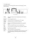
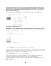
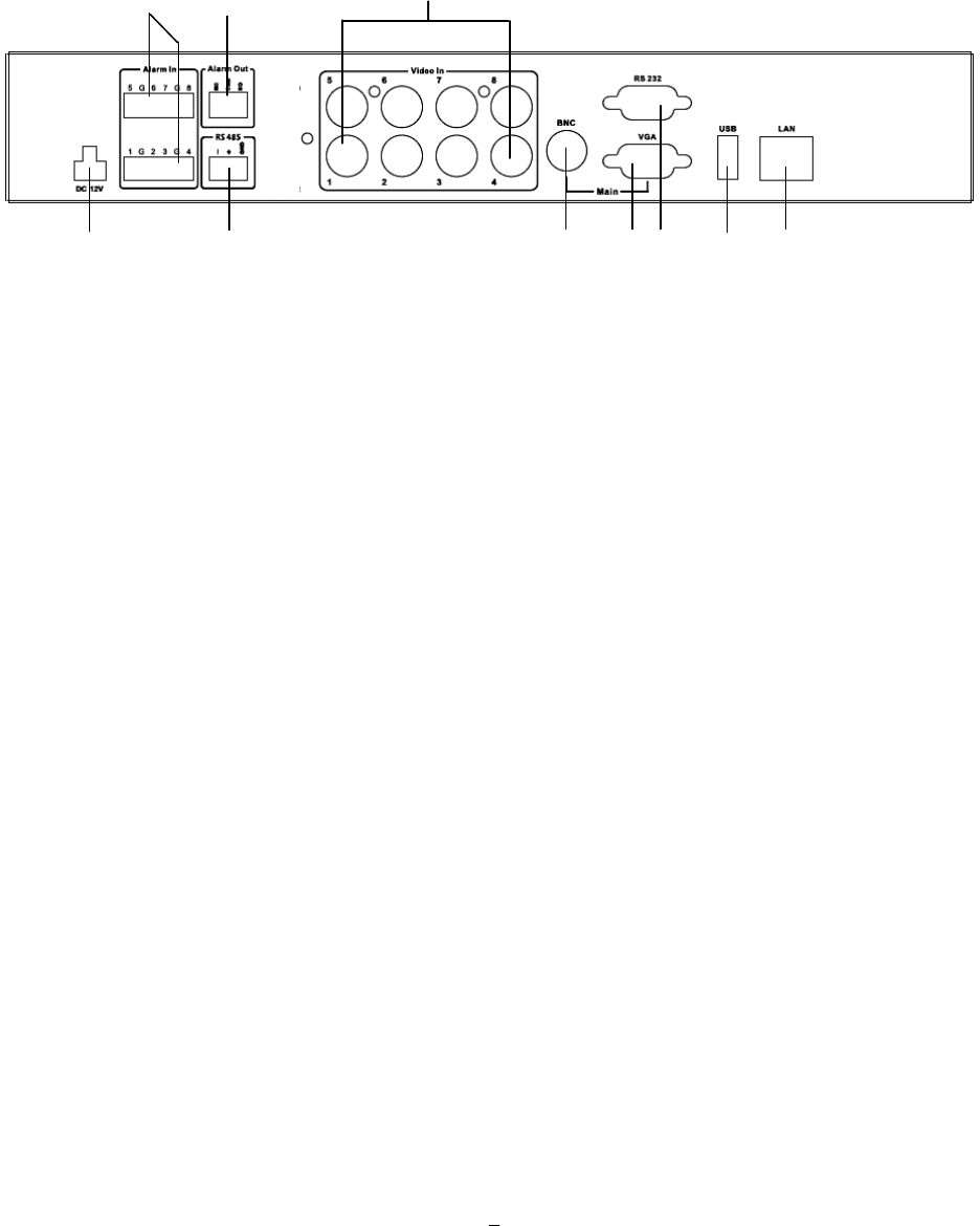
1.5 REAR PANEL
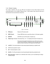
During initial setup you will be connecting your DVR to multiple input and output devices. This is done
through the rear panel.
Figure 1-2 Rear Panel
1 Video in Connect camera’s video output or other composite video source to the video input
connection.
2 Alarm Out N.C. or N.O. type alarm out (form “C”).
3 Alarm In Connect up to 4/8 alarm inputs, selectable between N.O./N.C. contacts.
4 POWER Plug the DC 12V power source provided into the power socket.
5 RS485 For remote control via RS-485 keyboards and telemetry control for attached PTZ
devices
6 BNC Main monitor composite BNC output for main monitor (live/playback/setup).
7 VGA Connect a VGA monitor to the VGA output connection. VGA resolution is 1280x1024.
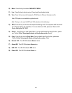
8 RS232 9-pin D-Sub control input for RS-232.
9 USB 2.0 USB port recommended for connecting the USB mouse.
10 LAN RJ-45 network connection 10/100 Mbps Ethernet. There are two LEDs on the LAN jack;
Green LED means network is connected, amber LED flickers when data is being
exchanged.
1
2
3
4 5 6 7 8 9 10