


EVERFOCUS ELECTRONICS CORPORATION
9
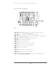
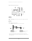
Basic Wiring Instructions
Please refer to diagram 1 on page 9 to assist you with this portion of the installation.
¾ Power: Connect the power source or adapter into the power socket shown in
diagram 1.
Please note: Do not plug the digital video recorder into the same
power source as the cameras.
¾ Cameras: Connect each cameras video output to the video input on the digital
video recorder shown in diagram 1.
Please note: At least one camera must be connected before the system
is running for the auto detection of video standard to take effect.
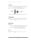
¾ Audio Input: The camera audio output or Microphone is connected to the
audio input terminal at the rear panel.
¾ Speaker: Connect the speaker or other audio listening devices to the audio
output terminal on the back of the digital video recorder.
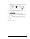
¾ Ethernet: The digital video recorder may be viewed from a PC via the LAN
connector using a RJ45 Ethernet cable.
¾ RS232/RS485: The digital video recorder may be controlled from a PC via
RS232/RS485.
Please note: This can be done using a serial cable.
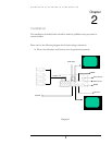
¾ Main Monitor: Connect the main monitor output connector to a main
monitor. The main monitor displays selected live or recorded cameras in any
available format.
Please note: The main monitor must be connected in order to make
configuration changes, enter the main menu, or do a playback at the
machine.
¾ Call Monitor: Connect the call monitor output connector to a call monitor.
The call monitor displays selected live cameras in full screen format.
Please note: The call monitor will only display one full screen camera
at a time.