MCP 1000 • Operation
Operation
MCP 1000 • Operation
3-2 3-3
Front Panel Features
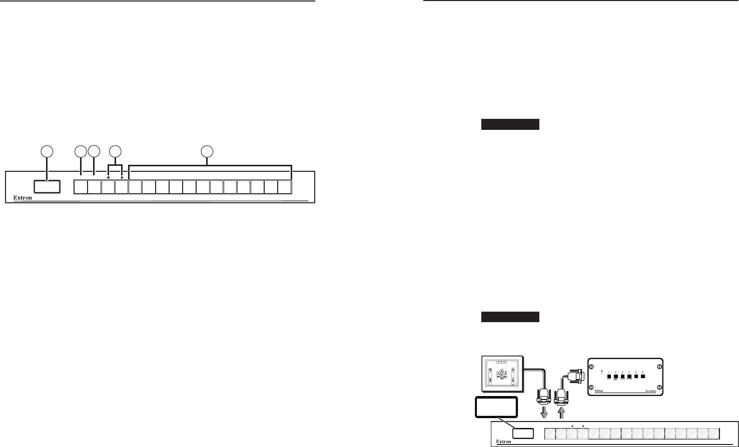
The buttons on the MCP 1000 front panel enable you to set up
and operate the MCP and to control a connected switcher.
N
In setup mode, the Menu, Next, W, and X buttons (
b
,
c
, and
d
in the illustration below) provide access to
the menus and submenus used for setting up the MCP.
When the MCP is in one of the operating modes (switcher,
output, room, or preset), these buttons function the same
as the other 12 selection buttons (
e
in the illustration).
See “Using setup mode,” later in this chapter, for more
information.
MCP 1000
MENU NEXT
51 2
3
4
MCP 1000 front panel
a
LCD window — This screen displays messages, menu
information, and selections you make by pressing front panel
buttons in different operating modes. (See “Setting Up the
Operation Mode,” later in this chapter, for more information.)
b
Menu button — In setup mode, press this button to access the
MCP’s menu system and step through the menus.
In the operating modes, this button becomes another selection
button.
c
Next button — In setup mode, after selecting a menu using
the Menu button, press the Next button to step through the
submenus.
In the operating modes, this button becomes another selection
button.
d
Right and left arrow buttons — In Setup mode, these buttons
let you make selections from the current submenu that you
accessed by pressing the Next button. From the submenus, you
can select the operating mode, a preset, the IP address, etc.
In the operating modes, these buttons become selection buttons.
e
Selection buttons — Press these buttons to issue SIS commands
to select an audio or video input, an output, or a preset,
depending on the operating mode specifi ed at setup. (These
buttons are disabled when the MCP is in setup mode.)
Application Examples
This section shows some examples of how the MCP 1000 can
be used to perform various functions with a variety of devices.
In view mode, the LCD window displays a title for the type
of operation (see "Title screen display," later in this chapter).
Numbers, names, and symbols can be created and inserted
in the button caps to identify the function of each button
(see "Changing the Front Panel Button Labels" in chapter 2,
"Installation").
CAUTION
Do not connect both a Matrix 3200/6400 BME
and an MCP 1000M (master) unit on the same
comm-link connection. Also, do not connect more
than one master on the same comm-link connection.
Both of theses units supply voltage to the comm-
link ports on pins A and B. Connect these pins
to only one power source. This does not apply to
MCP 1000S (slave) units.
Master applications (RS-232)
For each confi guration, a master sends out a specifi c SIS
command for each button that is pressed. If the master has
any slaves attached by comm-link, the master translates the
comm-link signals to SIS commands and sends them to the
device being controlled. The following examples include the
SIS command, in which i is the input number, o is the output
number, and p is the preset number.
CAUTION
Do not use delay or pause characters in RS-232
commands. Use contiguous SIS commands.
Audio-video switcher — SIS command: i!
MCP 1000
MENU NEXT
MCP 1000 Master
RS-232
1
23
4
56
AUD.VID.
SWITCHER
AUD.VID.
SWITCHER
Host
Control
Switcher to be controlled
MCP 1000M, SW6 switcher, and host computer
Pressing a panel button generates an SIS command to switch
audio and video for the corresponding button. For example,
press panel button 5 for input 5. If the switcher has fewer than
16 inputs, the MCP 1000 still sends out commands for unused
buttons, which may cause an error response from the switcher.
