


13
Model D2424 Quick Operation Guide
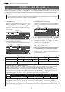
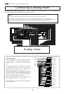
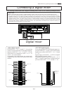
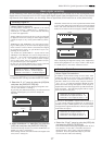
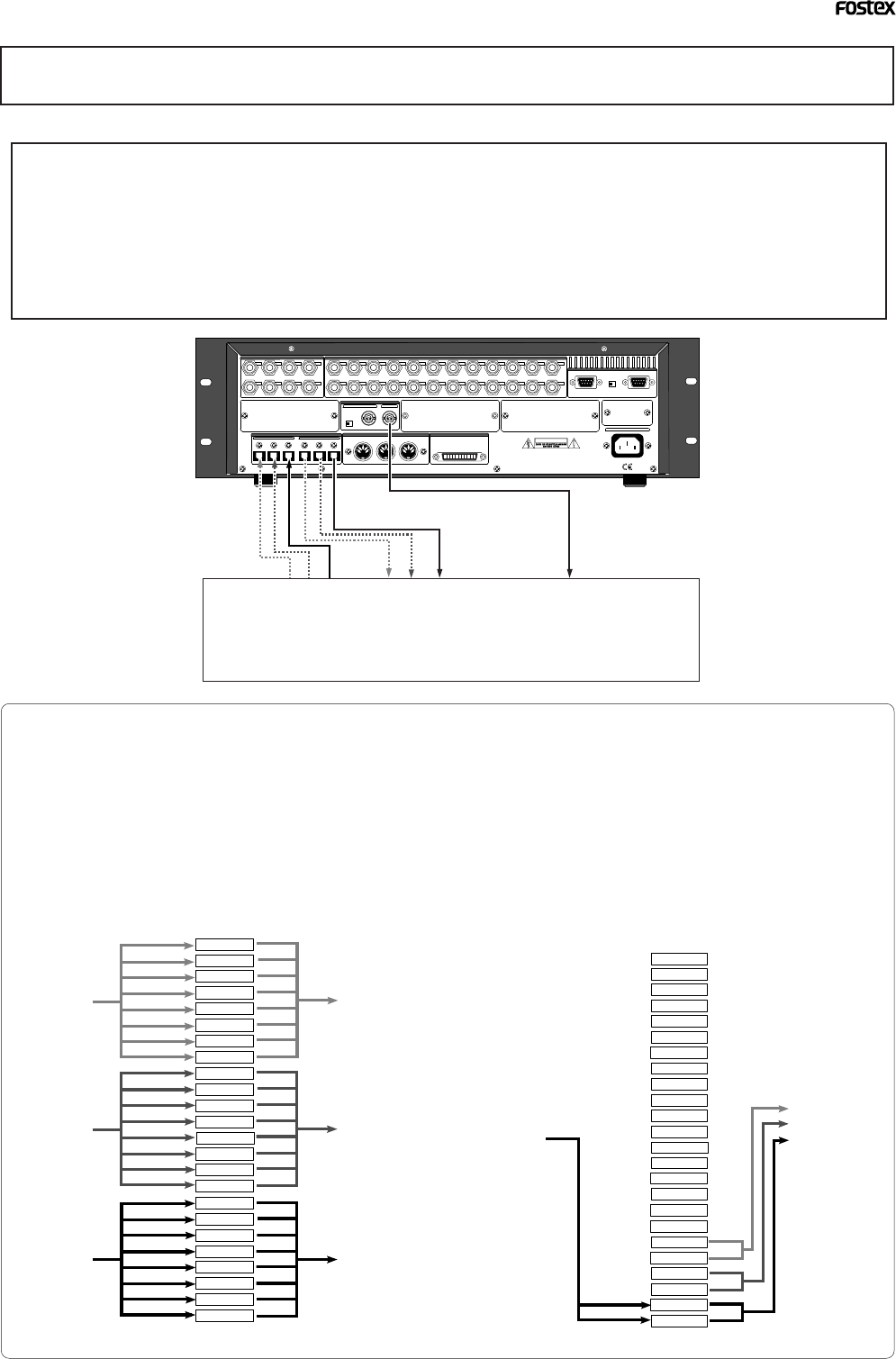
Connecting a digital mixer
<CAUTION>
• When connecting the recorder to a digital mixing console, make sure that the power of both units are off.
• The connection examples shown below work only when the current drive of the recorder is formatted with the
sampling frequency at 44.1 kHz or 48 kHz (regardless of quantization). If the drive is formatted with the sampling
frequency at 96 kHz or 88.2kHz, DIGITAL/DATA IN and OUT terminals are not usable and the following connection
examples will not work. To connect the recorder to a digital mixing console (or an external digital device) which
supports the 96 kHz (or 88.2kHz) sampling frequency, you will need to install the Model 8350 (8-channel AES/EBU
I/O card) which will be available soon to the recorder. For details about the Model 8350, consult the dealer you
purchased the recorder from or our sales office.
When making connections with a digital recording mixer, refer to the connectig example below.
75Ω
WORD
OUTPUTINPUT
OUTPUT
DATA
16 - 9
24 - 17
8 - 1
100Ω
RS422
THRU
AC-IN
INPUT
16 - 9
24 - 17
8 - 1
SCSI
ONOFF
REMOTE
MIDI
INPUT
THRU
OUTPUT
1
2
34
5678
1
234
13141516
5
6
7
8
1718
19
20
9
10
11
12
21
22
2324
NE PAS OUVRIR
CAUTION
AVIS:
RISQUE DE CHOC ELECTRIQUE
WARNING:
TO REDUCE THE RISK OF FIRE OR ELECTRIC
SHOCK, DO NOT EXPOSE THIS EQUIPMENT
TO RAIN OR MOISTURE.
ANALOG INPUT BALANCE [ +4dBu ] / UNBALANCE [ -10dBv ] ANALOG OUTPUT BALANCE [ +4dBu ] / UNBALANCE [ -10dBv ]
ONOFF
DATA
MIDI
WORD
SCSI
REMOTE
ANALOG OUTPUT BALANCE [ +4dBu ] / UNBALANCE [ -10dBV ]
ANALOG INPUT BALANCE [ +4dBu ] / UNBALANCE [ -10dBV ]
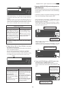
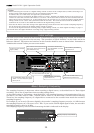
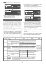
<adat digital signal>
DATA IN/OUT 1 - 8, 9 - 16 and 17 - 24 can all be
used for record/playback of adat digital signals.
Signals to DATA IN 1 - 8, 9 - 16 and 17 - 24 will,
respectively, be assigned to tracks 1 - 8, 9 - 16
and 17 - 24, and recorded.
At playback, the track outputs are respectively
assigned from each DATA OUT ports in the same
manner.
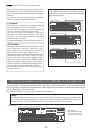
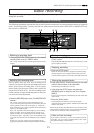
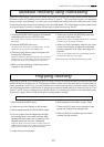
<S/P DIF digital signal>
At record/playback of S/P DIF digital signals, in-
put ports DATA IN 1 - 8 only can be used and the
output ports will be DATA OUT 1 - 8, 9 - 16 and
17 - 24.
Signals input to DATA IN 1 - 8 will be assigned
and recorded in tracks 1 and 2.
At playback, signals output from track 1 - 2, 3 -4
and 5 - 6 will be, respectively, assigned and out-
put from DATA OUT 1 - 8, 9 - 16 and 17 - 24.
DATA IN 1-8
TRK 1
TRK 2
TRK 3
TRK 4
TRK 5
TRK 6
TRK 7
TRK 8
TRK 9
TRK 10
TRK 11
TRK 12
TRK 13
TRK 14
TRK 15
TRK 16
TRK 17
TRK 18
TRK 19
TRK 20
TRK 21
TRK 22
TRK 23
TRK 24
DATA OUT 17-24
DATA OUT 9-16
DATA OUT 1-8
DATA IN 9-16
DATA IN 17-24
DATA IN 1-8
TRK 1
TRK 2
TRK 3
TRK 4
TRK 5
TRK 6
TRK 7
TRK 8
TRK 9
TRK 10
TRK 11
TRK 12
TRK 13
TRK 14
TRK 15
TRK 16
TRK 17
TRK 18
TRK 19
TRK 20
TRK 21
TRK 22
TRK 23
TRK 24
DATA OUT 17-24
DATA OUT 9-16
DATA OUT 1-8
Digital mixer