


18
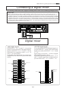
Model D2424 Quick Operation Guide
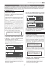
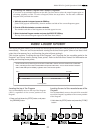
5. Select “D.out adat” by using the [JOG] dial, and
press the [EXECUTE/YES] key.
Now the Digital Out is set to "adat".
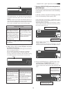
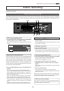
Setting the reference clock
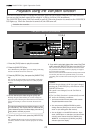
6. Select the “Clock Sel?” menu via using the [JOG]
dial, and press the [EXECUTE/YES] key.
The current reference clock is displayed together with
"Clock Sel?". The default is “Clock Sel? Int”.
Press the EXECUTE/YES key, and the current selection
will start flashing.
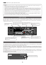
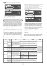
When setting "Digital In" (see the previous page) to
an "Async" mode ("adat:Async" or "SPDIF:Async"),
you must select whether the recorder is referenced
to the internal clock or word clock from an external
digital device. When setting "Digital In" to a "Sync"
mode ("adat:Sync" or "SPDIF:Sync"), the recorder is
referenced to the word clock received through the
external digital audio signal.
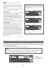
<About reference clock setting>
You must set the reference clock when setting "Digital
In" (see the previous page) to an "Async" mode
("adat:Async" or "SPDIF:Async"). You can select from
“Auto”, “Word” and “Video” in addition to the default
“Int”. Note that “Video” is available only when the op-
tional TC/SYNC card (model 8345) is installed.
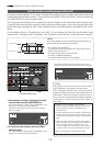
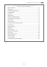
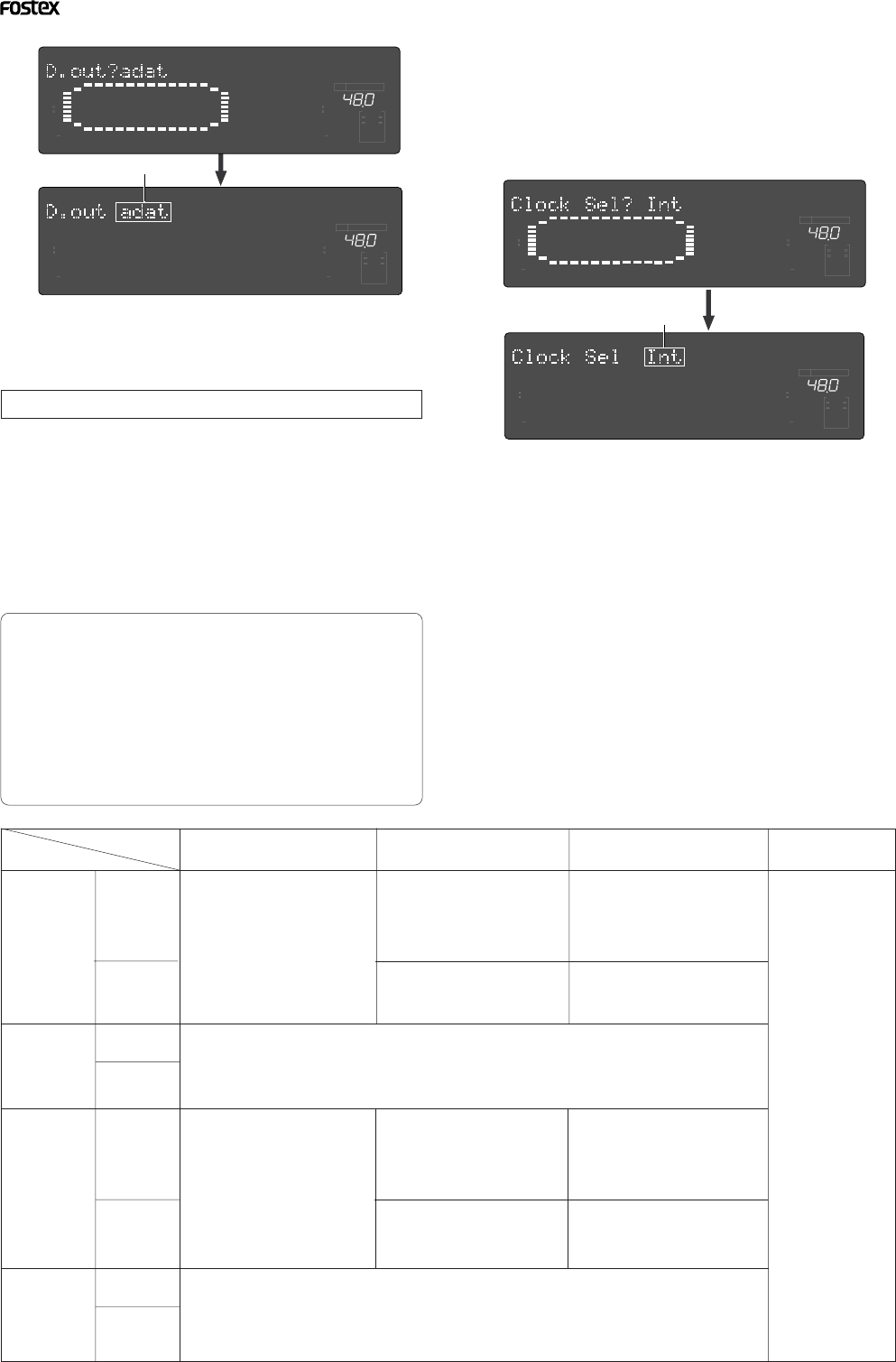
See the table below about the relation between the Digi-
tal In setting and reference clock.
7. Select the desired reference clock by using the
[JOG] dial, and press the [EXECUTE/YES] key.
The reference clock is now set to your desired clock.
When connecting the recorder to a digital mixing
console that can accept the word clock from the WORD
OUT of the recorder, set the recorder's reference clock
to “Int”. See the table below in other cases.
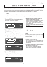
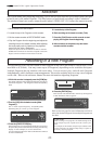
8. Press the EXIT/NO key or STOP button to exit the
SETUP mode.
The display shows the beginning of the disk with ABS
time base.
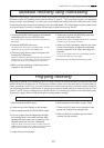
After complete “Digital In”, “Digital Out” and “Reference
Clock” settings, execute the basic recording in a similar
manner to "Basic analog recording" described earlier.
Flashing
Flashing
SPDIF :Async
SPDIF :Sync
adat :Async
adat :Sync
[D. in ?] setting
[Clock Sel ?]
setting
Int
Auto
Word
Video
clock received
from WORD IN
Available only when
installing the op-
tional Model 8345
TC/SYNC card. If
you try to select
“Video,” [Void w/o
Video] is displayed
and you cannot se-
lect it. See the ap-
pendix of the Refer-
ence manual for de-
tails.
Regardless of receiving or not re-
ceiving word clock from WORD IN,
the recorder is referenced to the
internal clock. When the recorder
receives correct digital signals, the
[DIGITAL] indicator lights in the
display.
When receiving word clock from
WORD IN, the recorder automati-
cally synchronizes to the incom-
ing clock, while the [DIGITAL],
[EXT], and [WORD] indicators
light in the display.
When receiving word clock from
WORD IN, the recorder synchro-
nizes to the incoming clock, while
the [DIGITAL], [EXT], and [WORD]
indicators light in the display.
Regardless of receiving or not receiving word clock from WORD IN, the recorder synchronizes to the
external S/P DIF digital signal. When the recorder receives correct digital signals, the [DIGITAL] and
[EXT] indicators light in the display. When Digital In is set to a SYNC mode, if you try to select [Clock
Sel?] menu, The display will show [Clock Sel D.in!] (indicating that the clock is set to Digital In!) and
the recorder ignores your operation.
Regardless of receiving or not receiving word clock from WORD IN, the recorder synchronizes to the
external adat digital signals. When the recorder receives correct digital signals, the [DIGITAL] and
[EXT] indicators light in the display. When Digital In is set to a SYNC mode, if you try to select [Clock
Sel?] menu, The display will show [Clock Sel D.in!] (indicating that the clock is set to Digital In!) and
the recorder ignores your operation.
Regardless of receiving or not re-
ceiving word clock from WORD
IN, the recorder is referenced to
the internal clock. When the re-
corder receives correct digital sig-
nals, the [DIGITAL] indicator lights
in the display.
When receiving word clock from
WORD IN, the recorder automati-
cally synchronizes to the incom-
ing clock, while the [DIGITAL],
[EXT], and [WORD] indicators
light in the display.
When receiving word clock from
WORD IN, the recorder synchro-
nizes to the incoming clock, while
the [DIGITAL], [EXT], and [WORD]
indicators light in the display.
no clock
received from
WORD IN
no clock
received from
WORD IN
no clock
received from
WORD IN
no clock
received from
WORD IN
clock received
from WORD IN
clock received
from WORD IN
clock received
from WORD IN
When no word clock is received,
the recorder is referenced to the
internal clock, while the [EXT] in-
dicator flashes.
When no word clock is received, the
[EXT] indicator flashes showing that
the recorder cannot be locked.
When no word clock is received,
the recorder is referenced to the
internal clock, while the [EXT] in-
dicator flashes.
When no word clock is received, the
[EXT] indicator flashes showing that
the recorder cannot be locked.
∞
42
OL
0
30
24
18
12
9
6
3
kHz
24
FS
BIT
SETUP
24
∞
42
OL
0
30
24
18
12
9
6
3
2322
21
20
19
18
17
1615141312
11
10
98765
4
3
2
1
CLOCK
∞
42
OL
0
30
24
18
12
9
6
3
kHz
24
FS
BIT
SETUP
24
∞
42
OL
0
30
24
18
12
9
6
3
2322
21
20
19
18
17
1615141312
11
10
98765
4
3
2
1
CLOCK
∞
42
OL
0
30
24
18
12
9
6
3
kHz
24
FS
BIT
SETUP
24
∞
42
OL
0
30
24
18
12
9
6
3
2322
21
20
19
18
17
1615141312
11
10
98765
4
3
2
1
CLOCK
∞
42
OL
0
30
24
18
12
9
6
3
kHz
24
FS
BIT
SETUP
24
∞
42
OL
0
30
24
18
12
9
6
3
2322
21
20
19
18
17
1615141312
11
10
98765
4
3
2
1
CLOCK