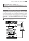
Model D2424 Reference Manual (Names and Functions)
17
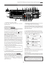
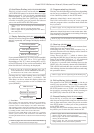
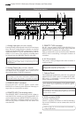
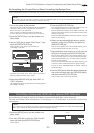
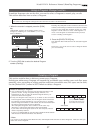
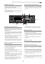
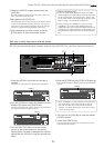
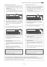
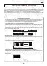
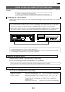
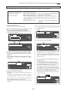
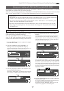
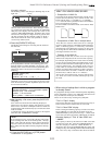
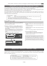
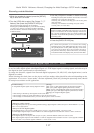
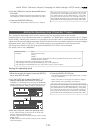
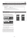
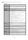
32. All Input LED [ALL INPUT]
This is lit when all track input monitors are set to
ON by pressing the [TRACK SHIFT] key while pressing
the [SHIFT] key, and extinguished when set to OFF.
While in the SETUP mode, it is also possible to
automatically set it to all input monitors while the
recorder is in the stop mode.
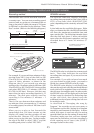
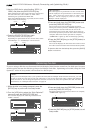
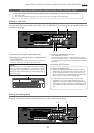
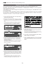
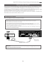
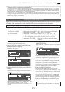
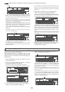
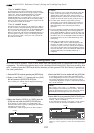
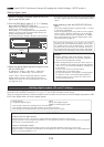
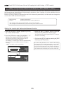
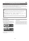
35. Foot switch jack [FOOT SW]
(Connector: PHONE jack)
Punch in/out (also for rehearsal) or PLAY/STOP of
the recorder can be done by foot by connecting the
optional foot switch.
The foot switch function can be changed in the SETUP
mode. It will not function for punch in/out function
in the initial setting.).
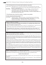
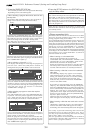
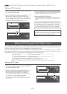
33. Track shift LED [9-16, 17-24] (green)
This is lit when the selectable recording track is
shifted to 9-16 or 17-24.
<Note>
Be sure to use an “unlatch type” foot switch if you use
a foot switch other than the Model 8051. Otherwise, a
malfunction could occur.
* Refer to page “
42
” for information about Punch In/
Out recording using the foot switch.
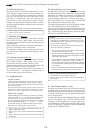
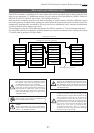
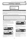
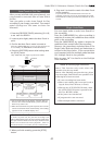
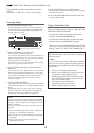
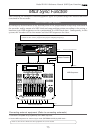
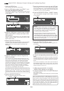
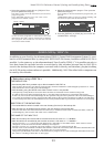
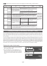
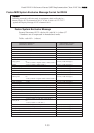
31. Shift key [SHIFT]
Press a key, or button while holding down the [SHIFT]
key to activate the following “shift-invoked”
functions.
VARI PITCH key
RECORD TRACK SELECT keys
TRACK SHIFT key
RECORD button
CLIPBOARD IN/OUT key
AUTO PUNCH IN/OUT key
AUTO RTN START/END key
EXIT/NO key
EXECUTE/YES key
DISP SEL key
EDIT key
SETUP key
UNDO/REDO key
Executes the envelope function of
the selected track.
Switches ON/OFF of the input
monitor for all tracks.
Switches SAFE-READY for all tracks.
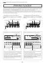
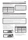
Executes preview of the stored point
of each memory key.
Ejects disk in the external SCSI drive.
Please see <Note> below.
Switches the slave mode ON/OFF.
Selects the time base.
Switches TC READY ON/OFF.
Enters the TC GEN setup mode.
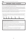
Enters the multiple undo executing
mode.
* Refer to page “
105
” for details on the SETUP mode.
* Refer to the
APPENDIX
at end of this manual in regards
to the TC generator mode.
* Refer to page "
64
" for details on multiple undo
function.
* Refer to the
Quick Operation Guide
in regards to editing
of Vari Pitch data.
* Refer to page "
62
" for details on preview.
* Refer to page "
60
" for details on the envelope function.
Enters the vari pitch data editing
mode.
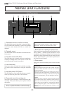
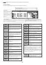
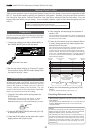
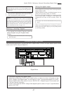
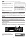
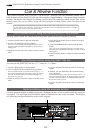
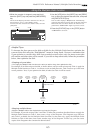
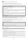
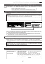
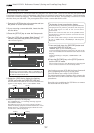
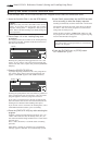
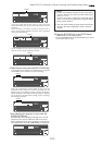
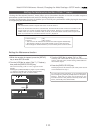
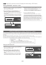
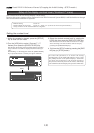
36. Meter display
This meter display shows the signal level and
settings.
* Refer to the “Display section” on page “
19
.”
<Note>
Ejecting or removing the backup SCSI disk is only
possible when the drive is set to [SCSI*] via the SETUP
mode "Setup of the drive." If the drive is set to [IDE],
eject it using the SCSI drive EJECT switch.
* For details, refer to
page 28
at end of this manual.
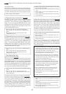
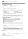
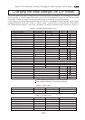
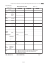
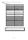
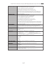
Key with SHIFT function
Function
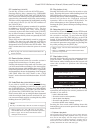
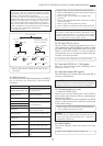
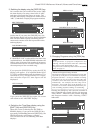
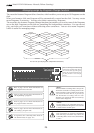
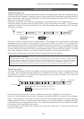
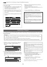
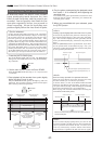
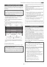
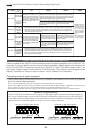
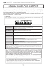
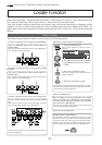
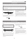
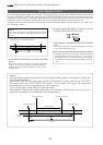
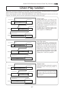
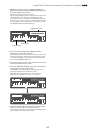
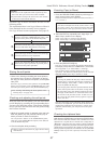
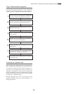
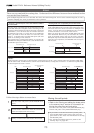
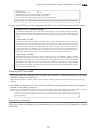
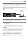
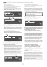
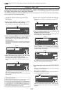
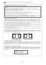
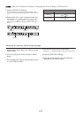
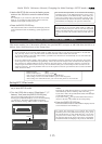
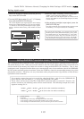
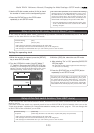
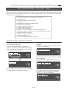
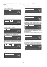
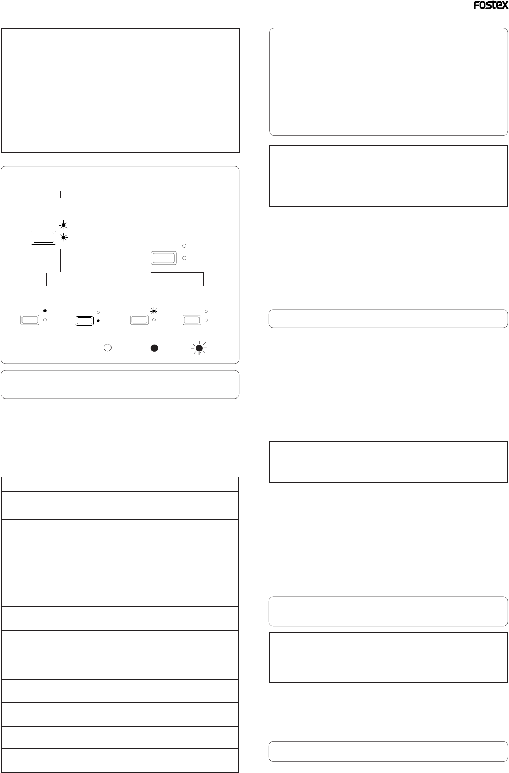
Auto Punch In/Out
Rehearsal Punch In/Out
using a foot switch or MMC
(Auto Punch mode ODD).
Punch In/Out mode
Rehearsal Take Rehearsal
Take
:go off :light up
:blink
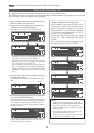
PUNCH
REHEARSAL
TAKE
AUTO
PUNCH
REHEARSAL
TAKE
AUTO
PUNCH
REHEARSAL
TAKE
AUTO
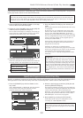
PUNCH
REHEARSAL
TAKE
AUTO
PUNCH
REHEARSAL
TAKE
AUTO
PUNCH
REHEARSAL
TAKE
AUTO
* Refer to page “
39
” for details about Punch In/Out
operation.
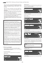
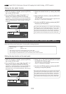
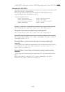
<Note>
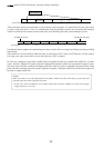
If a correct value is not stored, pressing the [AUTO
PUNCH] key will not enable the function, and the
message “Void Out Point!” will appear.
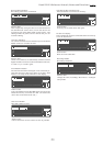
If a correct value is not stored, pressing the [AUTO
PUNCH] key will not turn on the function, and the
message “Void Out Point” will alert you. In this case,
set a correct value for the Auto Punch In/Out point.
Also, the function is not turned on when you press the
[AUTO PUNCH] key if the disk does not have enough
recording space. The display will indicate
“-**h**m**s**f Over.”
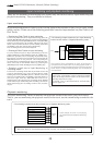
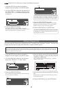
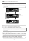
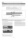
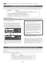
34. Hard disk access LED (green)
This LED lights up or blinks when the hard disk is
writing or reading data.
<CAUTION>
Do not turn the power off while this LED is lit or blinking.
Otherwise, data on the hard disk may be damaged.