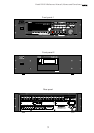
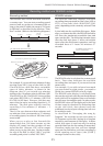
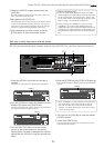
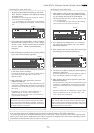
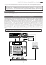
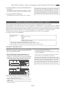
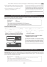
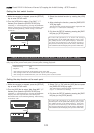
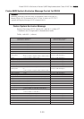
Model D2424 Reference Manual (Names and Functions)
14
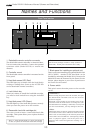
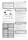
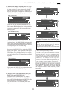
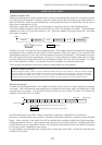
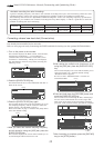
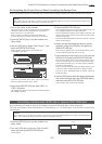
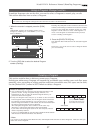
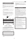
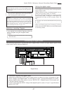
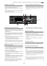
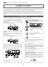
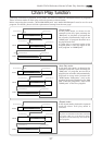
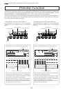
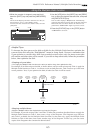
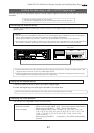
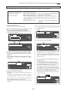
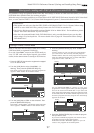
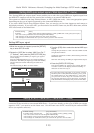
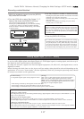
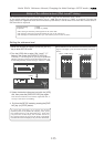
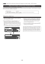
19. Jog/Shuttle dial
Jog dial (inside):
Turning the [JOG] dial while the recorder is stopped
performs digital scrubbing in either direction, which
allows you to check the audio and locate a point without
any change in pitch.
The [JOG] dial is also used to change values in the data
edit mode or when the pitch data is displayed. It also
allows you to select a parameter to set in Setup mode.
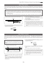
Shuttle dial (outside):
FWD and REW direction shuttle operation in the STOP
mode is possible at +/-1 ~ 64 times fast winding in the
no sound state. On the other hand, FWD and REW
direction shuttle operation in the PLAY mode is possible
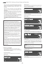
in the CUE playback mode at +1 ~ 8 and -1 ~ -7 times
speed while cueing. In addition, while in the display
edit mode, the editing point can be moved.
* Refer to page “
50
” for more information about the
editing the memory data.
* Refer to page “
105
” for more information about SETUP
mode.
* Refer to page “
60
” for more information about Digital
Scrubbing.
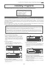
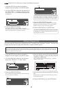
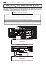
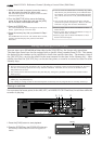
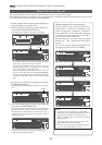
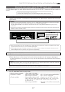
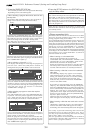
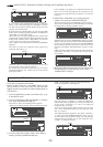
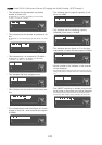
16. Recall key [RECALL]
This is pressed to call out the time figure (or bar/
beat/clk figure) data stored in locate number (0-
99). If the [LOCATE] key is pressed after pressing
this key, the RECALL LED will light and "Press
LOCATE**" is displayed. Next, by pressing the
[LOCATE] key after specifying a desired locate
number, the time figure in memory will be recalled
into the specified number and the recorder will enter
the edit mode.
Press the [LOCATE] key to execute this time figure.
* Refer to page "
54
" for more information about using
this key for the Locate operation.
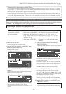
17. Next key [NEXT/NEXT TC]
If this key is pressed when in the recorder is in the
PLAY/STOP/F FWD or REW mode, locate will be
executed to the next memory point from the present
location point.
When inputting characters in the title edit mode, it
serves as a character short cut function.
The memory number can be advanced with each
press of this key when the recorder displays "Press
LOCATE: **".
18. Previous key [PREV/PREV TC]
If this key is pressed when the recorder is in the
PLAY/STOP/F FWD or REW mode, locate will be
executed to the one previous memory point.
When inputting character in the title edit mode, this
serves as a character short cut function.
The memory number selecting during display of
"Press LOCATE: **", the memory number can be
reverted with each press of this key.
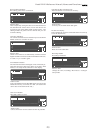
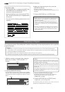
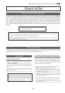
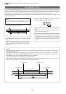
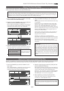
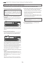
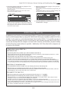
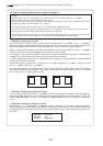
20. Vari-pitch key [VARI PITCH/P. EDIT]
Use this key to turn the Vari-pitch function on and
off. When this function is enabled, the corresponding
LED lights up. When this function is disabled, the
LED turns off. The range of pitch variation for
playback and recording is +/-6.0%, in 0.1% steps.
Press the [SHIFT] key, and then the [VARI PITCH]
key to display the current pitch data.
To change the pitch data, use the [JOG] dial to change
the value while the pitch data is displayed.
You can also change the playback speed when the
data is being played back with the Vari-pitch function
ON. To quit the pitch data display, press the [EXIT/
NO] key, or the [STOP] button.
<Notes>
* Even if the pitch data is 0.0% (no speed change),
pressing the [VARI PITCH] key will still turn on the
VARI PITCH function. The speed is not changed, but
the Vari Pitch is turned on.
* The Vari Pitch function will automatically turn off
under the following conditions:
1. You have turned off and on the power to this recorder.
The pitch data will be reset to 0.0%.
2. You have pressed the [EXECUTE/YES] key while holding
down the [SHIFT] key to turn the "SLAVE mode" on (the
setting pitch data remains).
3. You set "Digital In" of the SETUP mode to a SYNC mode
("SPDIF :Sync" or "adat :Sync") and the recorder is
locking to the external clock from DIGITAL IN or WORD
IN. In consequence, [DIGITAL] and [EXT] indicators light
in the display.
4. You have installed the optional Model 8345 TC/SYNC
card in this recorder and set the LTC OUT to [Gen.].
* Refer to “Quick Operation Guide” for more
information on the Vari-pitch function.
* Refer to pages “
80
” and “
83
” for more information on
Slave mode.
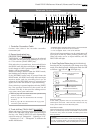
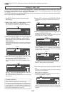
21. Fast Forward button [F FWD]
Pressing this button while the recorder section is
stopped will fast forward data at 30 times speed.
Pressing this button in Play mode will cue data (you
can hear sound during the fast forward operation)
at five times speed.
Pressing this button while holding down the [STOP]
button will initiate the “LOCATE ABS REC END”
operation, and immediately locate the end of the
recorded data on the Program (ABS REC END). (Refer
to the “STOP button” section for more information
about LOCATE ABS REC END.)