


Wireless Cable Voice Gateway CG3000/CG3100 User Manual
1-2 Connecting the Gateway
v1.0, July 2009
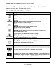
You can use the LEDs to verify status and connections. The following table lists and describes
each LED and button on the front panel of the gateway.
Table 1-1. LED and Front Panel Button Descriptions
LED Description
Power
• So
lid green. Power is supplied to the cable modem.
• Off. No power.
Downstream
• So
lid green. The unit is synchronized, and all four channels are in use (channel
bonding).
• Blinking. T
he unit is scanning for a downstream DOCSIS channel.
• Off. No downstream channels are locked.
Upstream
• Solid green. The unit is synchronized, and all four channels are in use (channel
bonding).
• Blinking. The unit is scanning for an upstream channel.
• Off.
No upstream channels are locked.
Internet
• So
lid green. The cable modem is online.
• Blinking. T
he cable modem is synchronizing with the cable provider’s CMTS.
• Off. The cable modem is offline.
LAN (
Ethernet)
• Green indicates 1,000 Mbps. Amber indicates 10/100 Mbps.
• So
lid. An Ethernet device is connected and powered on.
• Blinking. Data is being transmitted or received on the Ethernet port.
• Off.
No Ethernet device is detected on the Ethernet port.
Voice Ports
(1 and 2)
• Solid green. Registered with the Call Agent.
• Blinking. T
here is an active call.
• Slow blink. Phone is “on-hook,” registration with Call Agent is in progress.
• Off. No phones are connected to the voice port.
Button Description
Wireless
On/Off
Turn the wireless radio in the gateway on and off. The wireless radio is on by default. The
LED
located below this button indicates if the wireless radio is on or off.
Push 'N'
Connect (WPS)
Pushing this button opens a 2-minute window for the gateway to connect with other WPS-
ena
bled devices. For more information, about using the WPS method to implement secu-
rity, see the Wireless Cable Voice Gateway CG3000/CG3100 User Manual