


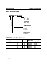

HYUNDAI MicroElectronics GMS90X5XC Series
6 Jan. 2001 Ver 1.0
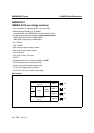
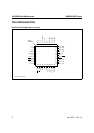
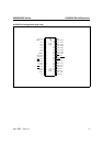
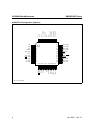
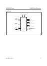
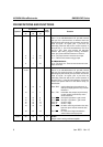
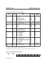
PIN DEFINITIONS AND FUNCTIONS
Symbol
Pin Number
Input/
Output
Function
PLCC-
44
PDIP-
40
MQFP-
44
P1.0-P1.7 2-9
2
3
2
1-8
1
2
1
40-44,
1-3
40
41
40
I/O
Port1
Port 1 is an 8-bit bidirectional I/O port with internal
pull-ups. Port 1 pins that have 1s written to them are
pulled high by the internal pull-up resistors and can be
used as inputs. As inputs, port 1 pins that are
externally pulled low will source current because of
the pulls-ups (I
IL
, in the DC characteristics). Pins P1.0
and P1.1 also. Port1 also receives the low-order
address byte during program memory verification.
Port1 also serves alternate functions of Timer 2.
P1.0 / T2 :Timer/counter 2 external count input
P1.1 / T2EX :Timer/counter 2 trigger input
In GMS90X52C/54C:
P1.0 / T2, Clock Out : Timer/counter 2 external count
input, Clock Out
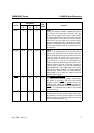
P3.0-P3.7 11,
13-19
10-17 5, 7-13 I/O
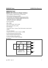
Port 3
Port 3 is an 8-bit bidirectional I/O port with internal
pull-ups. Port 3 pins that have 1s written to them are
pulled high by the internal pull-up resistors and can be
used as inputs. As inputs, port 3 pins that are
externally pulled low will source current because of
the pulls-ups (I
IL
, in the DC characteristics). Port 3 also
serves the special features of the 80C51 family, as
listed below.
11
13
14
15
16
17
18
19
10
11
12
13
14
15
16
17
5
7
8
9
10
11
12
13
P3.0 / RxD
P3.1 / TxD
P3.2 /INT0
P3.3 / INT1
P3.4 /T0
P3.5 /T1
P3.6 / WR
P3.7 /RD
receiver data input (asynchronous) or
data input output(synchronous) of serial
interface 0
transmitter data output (asynchronous)
or clock output (synchronous) of the
serial interface 0
interrupt 0 input/timer 0 gate control
interrupt 1 input/timer 1 gate control
counter 0 input
counter 1 input
the write control signal latches the data
byte from port 0 into the external data
memory
the read control signal enables the
external data memory to port 0
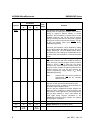
XTAL2 20 18 14 O
XTAL2
Output of the inverting oscillator amplifier.