


GMS90X5XC Series HYUNDAI MicroElectronics
Jan. 2001 Ver 1.0 41
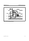
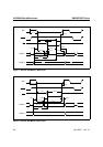
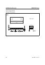
Figure 9. AC Testing: Input, Output Waveforms
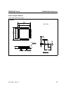
Figure 10. Float Waveforms
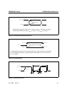
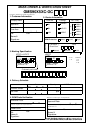
Figure 11. External Clock Cycle
AC Inputs during testing are driven at V
CC
−
0.5V for a logic ‘1’ and 0.45V for a logic ‘0’.
0.2V
CC
+
0.9
0.2V
CC
−
0.1
Test Points
V
CC
−
0.5V
0.45V
Timing measurements are made a V
IHmin
for a logic ‘1’ and V
ILmax
for a logic ‘0’.
V
LOAD
+
0.1
V
LOAD
−
0.1
Timing Reference Points
0.2V
CC
−
0.1
V
OH
−
0.1
V
OL
+
0.1
V
LOAD
For timing purposes a port pin is no longer floating when a 100mV change from load voltage
I
OL
/ I
OH
≥
20mA.
occurs and begins to float when a 100mV change from the loaded V
OH
/ V
OL
level occurs.
t
CHCL
t
CLCH
t
CHCX
t
CLCL
t
CLCX
0.2 V
CC
−
0.1
0.7 V
CC
V
CC
−
0.5V
0.45V