


4
Insignia NS-LCD32-09CA 32" LCD TV 720p
www.insignia-products.com
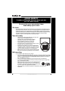
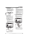
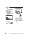
Note to CATV system installer
This reminder is provided to call the CATV
system installer’s attention to Article 820-40 of
the NEC that provides guidelines for correct
grounding and in particular, specifies that the
cable ground must be connected to the
grounding system of the building as close to the
point of cable entry as practical.
Mobile telephone warning
To avoid interference with your TV picture and
sound, operating problems, or even damage,
keep your cordless and cellular telephones away
from the TV.
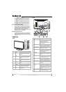
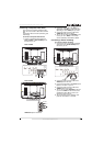
Features
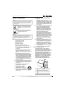
Front
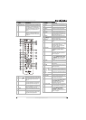
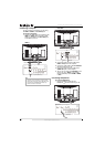
Back
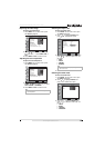
4 Grounding conductors
5 Antenna discharge unit
6 Grounding clamp
7 Antenna lead-in wire
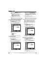
# Button Description
1 VOL+ Press to increase the volume. In Menu
mode, functions as the right arrow to
go to the next menu or increase a
setting.
2 VOL– Press to decrease the volume. In Menu
mode, functions as the left arrow to go
to a previous menu or decrease a
setting.
3
CH
Press to go to the next higher channel.
In Menu mode, functions as the up
arrow.
4
CH
Press to go to the next lower channel.
In Menu mode, functions as the down
arrow.
5 MENU Press to show the on-screen menu.
6 SOURCE Press to cycle through the available
input sources. In Menu mode,
functions as the ENTER button.
7 POWER Press to turn on your TV or put it into
Standby mode.
1
2
3
5
6
4
7
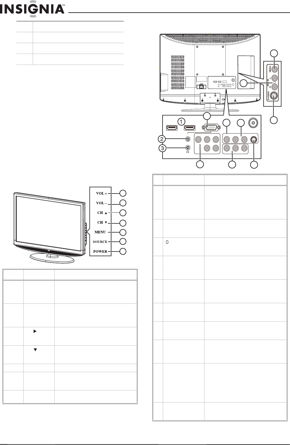
# Jack Description
1 HDMI 1/HDMI 2 Connect HDMI devices to these jacks.
You can connect a DVI device to either
of these jacks by using an
HDMI-to-DVI adapter. For more
information, see “Connecting an HDMI
device” on page 7.
2 PC IN AUDIO Connect the audio for a computer to
this jack. For more information, see
“Connecting a computer” on page 10.
3
(headphone)
Connect headphones to this jack. For
more information, see “Connecting
headphones” on page 10.
4 COMPONENT Connect a component video device to
these jacks. For more information, see
“Connecting a component video
device” on page 7.
5 AV OUT Connect a VCR for recording to these
jacks. For more information, see
“Connecting a VCR for recording” on
page 9.
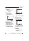
6 AV 1 IN S-VIDEO Connect an S-Video device to this jack.
For more information, see “Connecting
an S-Video device” on page 8.
7 PC IN VGA Connect the video for a computer to
this jack. For more information, see
“Connecting a computer” on page 10.
8 AV 1 IN VIDEO Connect a composite video device to
this jack. For more information, see
“Connecting a composite video device”
on page 9.
9 AV 1 IN L and R
audio
Connect the audio for the composite or
S-Video device connected to the AV 1
IN VIDEO or AV 1 IN S-VIDEO jack. For
more information, see “Connecting a
composite video device” on page 9 or
“Connecting an S-Video device” on
page 8.
10 AV 2 IN S-VIDEO Connect an S-Video device to this jack.
For more information, see “Connecting
an S-Video device” on page 8.
750
S-VIDEORLVIDEOPrPbYAUDIO
HDMI 1
PC IN
AV 1 IN
AV OUTCOMPONENT
VGA
HDMI 2
RLVIDEORL
7
4
8
5
6
9
10
11
12