


15
Front & Rear Panels
—Continued
A
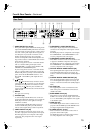
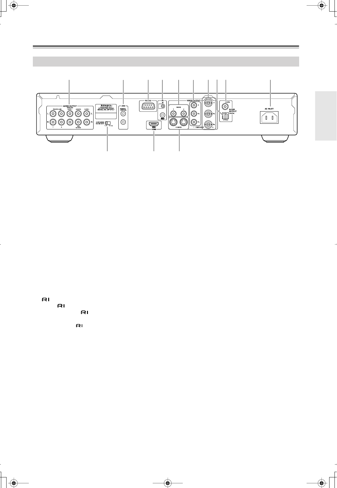
AUDIO OUTPUT [20, 22, 23]
These jacks make up the multichannel analog audio
output. The FRONT/D.MIX jacks can be connected
to a stereo input on a TV, hi-fi amp, or other compo-
nent. The 1 and 2 jacks output the same signals, so
use either pair. If you use this connection, in the
Speaker Configuration (page 48), set the Sub-
woofer, Center Speaker, and Surround Speaker set-
tings to Off, so that 5.1-channel DVD audio is down
mixed into two channels.
If you’re using an AV receiver or surround decoder
with a 5.1-channel analog audio input, use the
FRONT/D.MIX 1 or 2 jacks and the SURR 1 L/R,
CENTER, and SUBWOOFER jacks.
If you’re using an AV receiver or surround decoder
with a 7.1-channel analog audio input, connect the
SURR 2 L/R jacks to your amp’s surround back L/R
jacks, and set the SURR MODE switch to “1+2.”
The SURR 1 and SURR 2 jacks output the same
signals.
B
jack [23]
These (Remote Interactive) connectors can be
connected to the connectors on your other Inte-
gra/Onkyo AV components for interactive control.
Connecting an cable only does not make the
system operational. You must also connect the audio
cables as well.
C
RS 232
This port is for servicing.
D
IR IN/OUT [25]
A commercially available IR receiver can be con-
nected to the IR IN jack, allowing you to control the
DVD player when it's out of sight, for example,
installed in a cabinet.
A commercially available IR emitter can be con-
nected to the IR OUT jack to pass IR (infrared)
remote control signals along to other components.
E
VIDEO OUTPUT 1/2 [20]
These RCA/phono connectors can be used to con-
nect TVs or projectors with composite video inputs.
The DVD player has two composite video output
connectors. They output the same video signal
respectively.
F
COMPONENT 1 VIDEO OUTPUT [21]
These jacks output component video and can be
connected to an component video input on a TV or
projector.
The DVD player has two component video outputs,
the COMPONENT 1 and COMPONENT 2, how-
ever, they output the same video signal.
G
COMPONENT 2 VIDEO OUTPUT [21]
These BNC connectors can be used to connect a TV
or projector with BNC component video inputs.
The DVD player has two component video outputs,
the COMPONENT 1 and COMPONENT 2, how-
ever, they output the same video signal.
H
OPTICAL DIGITAL AUDIO OUTPUT [22]
This optical digital audio output can be connected to
an optical digital audio input on a hi-fi amp, AV
receiver, or surround sound decoder (Dolby Digital,
DTS).
I
COAXIAL DIGITAL AUDIO OUTPUT [22]
This coaxial digital audio output can be connected
to a coaxial digital audio input on a hi-fi amp, AV
receiver, or surround sound decoder (Dolby Digital,
DTS).
J
AC INLET [26]
The supplied power cord is connected here. The
other of the power cord should be connected to a
suitable wall outlet.
K
SURR MODE switch [23]
This switch is used to turn the AUDIO OUTPUT
SURR 2 on or off. To use this output, set the switch
to “1+2.” The SURR 2 jacks output the same signals
as the SURR 1 jacks.
L
HDMI OUT [24]
This HDMI output can be used to connect a TV or
projector with an HDMI input. This HDMI connec-
tor outputs digital audio and digital video.
M
S VIDEO OUTPUT 1/2 [21]
These connectors can be used to connect TVs or
projectors with S-Video inputs.
The DVD player has two S-Video output connec-
tors. They output the same video signal.
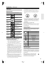
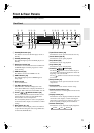
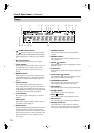
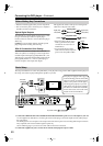
Rear Panel
432 65 J
LK
981
M
7