


14
Connections
INPUT 1
INPUT 2INPUT 3
AUDIO
L
R
MONO
MONO MONO
VIDEO
S-VIDEO
OVER
OVER
OVER
IN
IN
INPUT
A
SPLIT
OUT
INPUT
B
75Ω
( VHF / UHF )
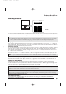
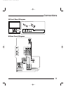
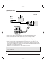
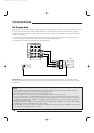
1) Connect a coaxial cable out from the cable TV wall outlet or external antenna into the RF Input A.
2) Connect a coaxial cable out from the Cable Split Out RF jack into the RF input on the Cable Box.
3) Connect a coaxial cable out from the RF Output jack of the cable box into the RF input on the VCR.
4) Connect a coaxial cable out from the VCR RF Output jack into the television’s RF Input B.
5) Connect the yellow video cable from the VCR’s Video Output jack to the TV’s Video Input 1 jack.
6) Connect the white audio cable from the VCR’s Left Audio Output jack to the TV’s Left Audio Input 1 jack.
7) Connect the red audio cable from the VCR’s Right Audio Output jack to the TV’s Right Audio Input 1 jack.
• If you are connecting a mono sound VCR it will have only one audio out jack. Connect it to the TV’s left audio
input jack.
• The VCR signal will be available on Input 1 on the Input Menu (see page 54) if the connection shown above is used.
• Coaxial cables are not included with the television.
• Please consult your VCR’s owners manual for more information on its operation.
VCR
Yellow
White
Red
CABLE
BOX
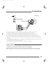
Note:
• When recording a program from a cable box which is connected as shown above, switch the antenna mode to INPUT-A
before starting to record with the VCR. If you want to watch the program which is being recorded, use the INPUT button
to choose the VIDEO input.
Diagram #3
AV-61S902(E) 1/12/01 3:15 PM Page 14