


17
HOW TO USE EXTERNAL
CONTROL
Ⅵ ABOUT EXTERNAL CONTROL
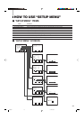
This multi-format monitor has two external control terminals. One is the MAKE terminal, which controls the monitor by connecting
the terminals with many functions to the ground (GND) terminal. The other is the RS-232C terminal, which allows the monitor to
be controlled by a PC via serial communication.
Control priority is in the following order; the MAKE terminal > the RS-232C terminal > the buttons on the front panel.
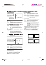
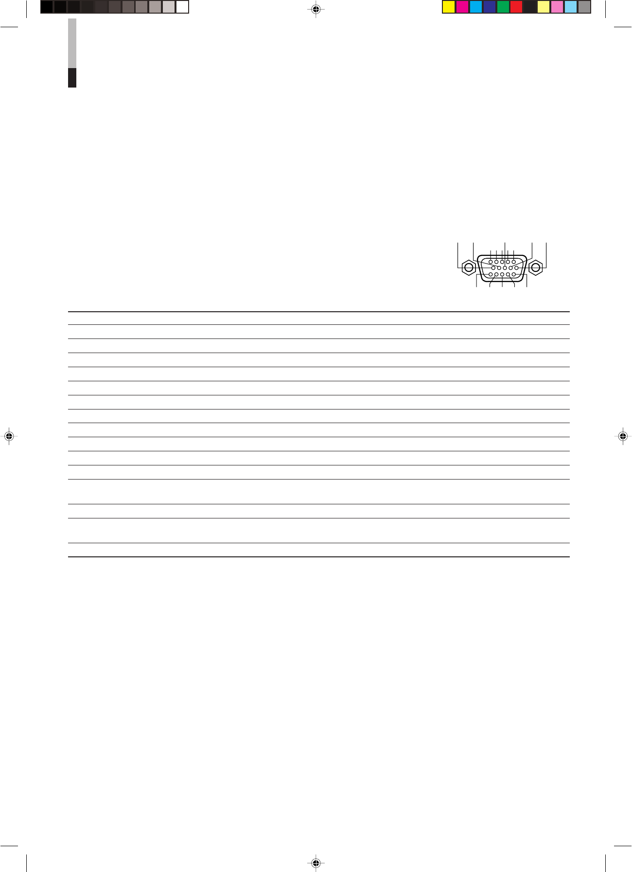
10 9 8
54321
7
6
1415 13 12 11
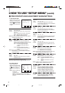
*1 : OFF stands for disconnection, and ON stands for short-circuit.
*2 : Selects the area marker size from AREA MARKER (setting on the main unit) or AREA MARKER-R (setting on the remote control) setting.
*3 : The STATUS function is activated when the connection to the STATUS terminal is changed (ON to OFF, or OFF to ON). The monitor’s status
is displayed for 3 seconds.
*4 : Setting REMOTE ENABLE to ON enables remote control from the MAKE terminal.
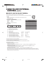
The Names and Functions of Terminals
No. Names Functions Operations (OFF p[ ON) *1
1 TALLY Puts on the tally lamp. Put on Put off
2 INPUT A Changes the input to INPUT A Not change Change
3 INPUT B Changes the input to INPUT B Not change Change
4 INPUT C Changes the input to INPUT C Not change Change
5 INPUT D Changes the input to INPUT D Not change Change
6 INPUT E Changes the input to INPUT E Not change Change
7 INPUT F Changes the input to INPUT F Not change Change
8 COLOR OFF Changes the picture black-and-white. Not change Change
9 AREA MARKER Displays the area marker. Not display Display
10 ASPECT Changes the screen ratio to 16:9 4:3 16:9
11 UNDER SCAN Makes the screen under-scan Over-scan Under-scan
12 MARKER Selects the type of the area marker Selection in the main unit Selection in the remote *2
control
13 STATUS Displays the monitor’s status Display *3
14 REMOTE ENABLE Makes the external control form the Invalid Valid *4
MAKE terminal valid or invalid
15 GND Used as a ground terminal ––
Ⅵ HOW TO USE THE MAKE TERMINAL
Connections
Connect (short-circuit) the 15th terminal (GND) to each of the 1st through 14th terminals in the
3-lines 15-pins D-sub connector. The functions of each terminal are listed below.
Operation
1. Set REMOTE ENABLE to ON.
2. Short-circuit or disconnect the desired terminal.
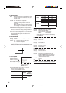
Changing the Signal Input.
Changing the Signal Input
1. Set REMOTE ENABLE to ON.
2. Short-circuit the desired INPUT terminal.
3. Disconnect the INPUT terminal selected above. The signal input is actually changed after the disconnection has been
completed.
NOTE : When more than two terminals are selected (short-circuited) from INPUT A through INPUT F, the signal input is not
changed.
To control INPUT A through INPUT F, we recommend using the interlock switch, which turns off a switch when another
switch is turned on.
Untitled-1 01.3.27, 9:5817