


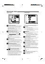
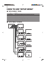
5
REAR/SIDE VIEW
<Rear Panel>
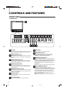
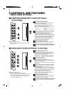
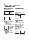
COLOR OFF button/lamp
Press the COLOR OFF button. The button lights and the
screen becomes monochrome. When the COLOR OFF
button is pressed while lit, the light goes off and the
normal screen is restored.
Use this function to confirm the noise in the brightness
signal or to confirm the white balance.
NOTE: This function is invalid with the RGB-input screen.
SCREENS CHECK button/lamp
Press the SCREENS CHECK button. The button lights
and the screen changes in the following order:
Normal screen[Red screen[Green screen
Blue screenp
Press the SCREENS CHECK button when the blue
screen is displayed. The light goes off and the normal
screen is restored.
Use this function to confirm or adjust CHROMA or
PHASE.
NOTE: This function is invalid with the RGB-input screen.
ASPECT button/lamp
When the ASPECT button is pressed while the screen
ratio is 4:3, the button lights and the screen ratio changes
to 16:9. When the ASPECT button is pressed while lit, the
light goes off and the normal screen is restored.
NOTE: This function is invalid with the RGB-input screen.
AREA MARKER button/lamp
When the AREA MARKER button is pressed while the
screen ratio is 16:9, the button lights and the white
marker is displayed. This shows the screen size (area)
set on the menu. When the AREA MARKER button is
pressed while lit, the light goes off and the normal screen
is restored.
NOTE: This function is invalid with the RGB-input screen.
– INPUT SELECT buttons/lamps
Press the unlit button. The button lights and the input
signal is changed. (any other lit button goes off.)
When the lit button is pressed, the status of the current
input signal is displayed (for approx. 3 seconds). Buttons
A through F correspond to the signals input via the input
cards installed in SLOT 1 through SLOT 3.
A, B : select the picture from the SLOT 1 input card.
C, D : select the picture from the SLOT 2 input card.
E, F : select the picture from the SLOT 3 input card.
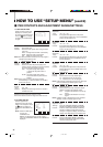
12
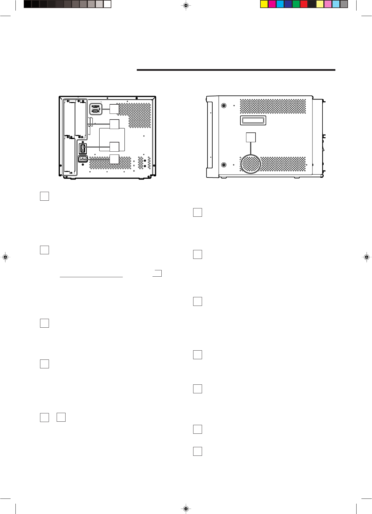
MAKE
SLOT1
RS-232C
REMOTE
SLOT2
SLOT3
MAIN POWER
24
25
26
27
28
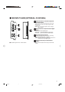
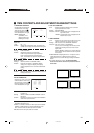
<Side Panel>
Refer to pages 8 and 9 for correspondence between the
input terminals and the INPUT SELECT buttons.
Power lamp
Unlit : The main power is OFF.
Orange : The main power is ON, but the monitor’s power
is OFF (in stand-by mode).
Green : The main power is ON, and the monitor’s power
is ON (in normal operation mode).
POWER switch
Press the power switch to turn the monitor’s power ON or
OFF when the main power is ON.
NOTE: When RUSH DELAY TIME is set to MODE 2 in
the set-up menu, it takes approx. 3.2 seconds for
the power to actually turn ON after the power
switch is pressed.
REMOTE (external control) terminals
Terminals for controlling the monitor from an external unit.
RS-232C terminal (Upper):
Enables the monitor to be controlled from a personal
computer via serial communication.
MAKE terminal (Lower):
Enables the monitor to be controlled by closing the circuit
(point of contact) connected to the terminal.
Input card slots (SLOT 1 — SLOT 3)
Optional input cards can be installed in these slots. Input
cards are not provided when you purchase the monitor.
NOTE: It is not possible to input video or audio signals to
the monitor when no input cards are installed.
Main power switch
Press the switch to turn the main power ON or OFF.
When the main power is ON, the power lamp on the front
panel lights in yellow and the monitor enters the stand-by
mode.
I : ON ⅜ : OFF
AC inlet
Power input connector. Connect the provided AC power
cord to an AC outlet (120 V AC, 50 Hz/60 Hz).
Built-in speaker (monaural)
Outputs the input audio.
13
14
15
16
21
22
23
24
25
26
27
28
[
Untitled-1 01.3.27, 9:585