


5
1
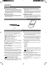
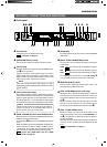
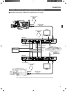
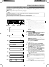
Intercom jack
Connect the intercom headset to this jack.
REF.
: “Intercom” on page 14.
2
[INTERCOM LEVEL] control
Use this knob to adjust the intercom earphone volume.
3
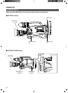
[TALLY] lamp
This lamp lights when a signal is input to the TALLY termi-
nals
2
on the rear panel.
It lights in red when a tally signal is input to the TALLY
PGM terminal on the rear panel or in green when a tally
signal is input to the TALLY PVW terminal. It blinks in red
when there is a CALL signal from the camera.
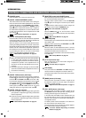
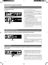
6
[GAIN] lamp
This lamp lights when the gain control is in the VARIABLE
GAIN mode.
7
[GAIN - STEP LOW/MID/HIGH] switch
The gain value can be selected according to the position
of this switch.
HIGH :
REF.
Gain value set by item “5F: GAIN HIGH” on page 25.
MID :
REF.
Gain value set by item “5E: GAIN MID” on page 25.
LOW :
REF.
Gain value set by item “5D: GAIN LOW” on page 25.
The selected gain value is shown in the LCD display
)
every time that the position of this switch is changed.
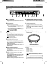
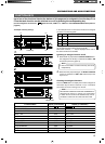
8
[MASTER BLACK] control
Use this knob to adjust the pedestal level, which is the
black reference (master black) value.
9
[IRIS - AUTO/MANU] button (with lamp)
When this button is pressed so that the lamp in it lights the
lens iris is set to the manual iris control mode. The lens iris
level may be adjusted in this mode by using the IRIS con-
trol
0
.
When this button is pressed so that the lamp in it turns off,
the lens iris is set to the auto iris control mode.The auto
iris level can be fine adjusted with the IRIS control
0
.
0
[IRIS - CLOSE-OPEN] control
When the manual iris control mode is set (which is indi-
cated by the lighting of the lamp in the AUTO/MANU but-
ton
9
), use this knob to adjust the iris aperture between
CLOSE and OPEN.
When the iris mode is AUTO (when the lamp in the button is
not lit up), the auto iris level can be fine adjusted with this
knob.
REF.
“Iris Adjustment” on page 17.
INTRODUCTION
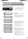
CONTROLS, CONNECTORS AND INDICATORS
Ⅵ Front panel
4
[CALL] button (with lamp)
The camera operator can also be called without using the
intercom. When this button is pressed once, the button lamp
lights up and the tally lamp on the camera blinks to inform
the camera operator of a call. Pressing this button again
turns off both the button lamp and tally lamp on the camera.
CALLTALLY
INTERCOM
LEVEL
FULL AUTO F1
SHUTTER
GAIN
F2
F3
MENU/SHUTTER GAIN
PAINT AUTO
BR
W.BAL
AUTO
MANU
WHITE MASTER BLACK
POWER
I
O
IRIS
STEP
SHUTTER
MENU
PUSH-ON
DOWN UP
VARIABLE
PUSH-ON
HIGH
LOW
B
A
PRESET
CLOSE OPEN
MID
DOWN UP
F4
BARS
REMOTE CONTROL UNIT RM-P210
@#$%*()
2
3 4 567 8 9 0 !
¤ ⁄ &
1
^
The order of priority among the above signals are; CALL
(red blinking), TALLY PGM (red lighting) then TALLY PVW
(green lighting).
NOTE
5
[GAIN - VARIABLE] control with ON/OFF button
When the button is pressed, the VARIABLE GAIN mode is
switched ON and OFF alternately.
The GAIN lamp
6
lights when the VARIABLE GAIN mode
is ON.
When the GAIN mode is set to VARIABLE, the GAIN value
can be varied from 0.1 dB (or 1.0 dB) to 18 dB in 0.1 dB (or
1.0 dB) steps. The variation per step and the maximum
gain value can be changed under the following items.
REF.
: Items “5B: V. GAIN STEP” and “5C: V. GAIN
MAX” on page 25.
When the CALL button is pressed during VF-P400 op-
eration, the picture on the viewfinder screen may vi-
brate. However, this is not a malfunction.
NOTE