


7
1
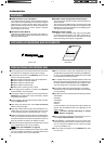
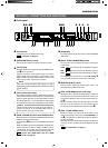
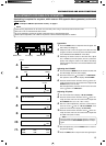
[AC ` IN] connector
Connect this socket to a commercial power supply outlet
using the power cord provided.
2
[TALLY] terminals
These terminals input the tally signals.
● When the contact between the PGM (Program) and C
(Common) terminals is closed, the TALLY lamp
3
on
the front panel lights in RED.
● When the contact between the PVW (Preview) and C
(Common) terminals is closed, the TALLY lamp
3
on
the front panel lights in GREEN.
REF.
: “Tally Input” on page 14.
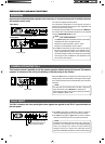
3
[INTERCOM] terminals
These terminals input and output the intercom signals.
In a system composed of multiple cameras and remote
control units, the intercom function provides intercommu-
nication between operators.
REF.
: “Intercom” on page 14.
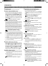
4
[AUX VIDEO INPUT] connectors
These connectors are used to input the return video sig-
nal, which returns the SEG (Special Effects Generator) or
switcher output signal to the camera viewfinder.
The two terminals are loop-through connected inside to
enable a bridge connection.
They are terminated automatically when they are not
bridge-connected.
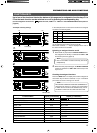
5
[GENLOCK INPUT] connectors
These connectors are used to input the VBS/BB signal for
use in genlocking.
They are terminated automatically when they are not
bridge-connected.
6
[R/R-Y, G/Y, B/B-Y] component video signal
output connectors
The settings of the output signals from these connectors
can be switched between RGB, R-Y/Y/B-Y and Y/C using
the SIG SELECT switch on the camera adapter or by us-
ing the menu setup of the camera.
When Y/C is selected, the Y signal is output from the G
connector and the C signal is output from the R connector.
7
[COMPOSITE VIDEO] signal output connectors
These terminals output two lines of VBS (composite video)
signals.
8
Y/C OUT connector (4-pin)
This connector outputs the separate Y/C video signals.
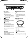
INTRODUCTION
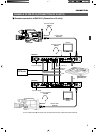
CONTROLS, CONNECTORS AND INDICATORS (CONTINUED)
Ⅵ Rear panel
HGCCPVWPGM
TALLY INTERCOM AUX VIDEO INPUT GENLOCK INPUT VIDEO OUTPUT Y/C OUT
CAMERA CABLE
R/R-Y B/B-Y
COMPOSITE VIDEO
G/Y
RTS
984 5 6 71 2 3
This connector outputs Y/C signals only when Y/C is
selected as the output from the R/R-Y, G/Y and B/B-Y
connectors
6
.
NOTE
9
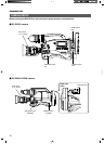
[CAMERA CABLE] connector (26-pin)
Connect this socket to a camera using the optionally avail-
able camera cables.
A menu setup is required according to the cables in use.
REF.
: “Setup of Camera Cable Length” on page 12.
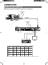
The VC-P110 series camera cables that can be used to con-
nect a camera to the RM-P210 are available in four lengths as
listed below.
VC-P110 : 5 meters
VC-P112 : 20 meters
VC-P113 : 50 meters
VC-P114 : 100 meters
Camera Cables (Optional)
● If it is required to extent the cable, use the KA-280
extension connector.
● The total cable length should not exceed 100 meters.
NOTE