


43
CN607
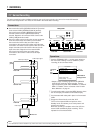
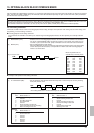
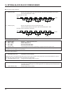
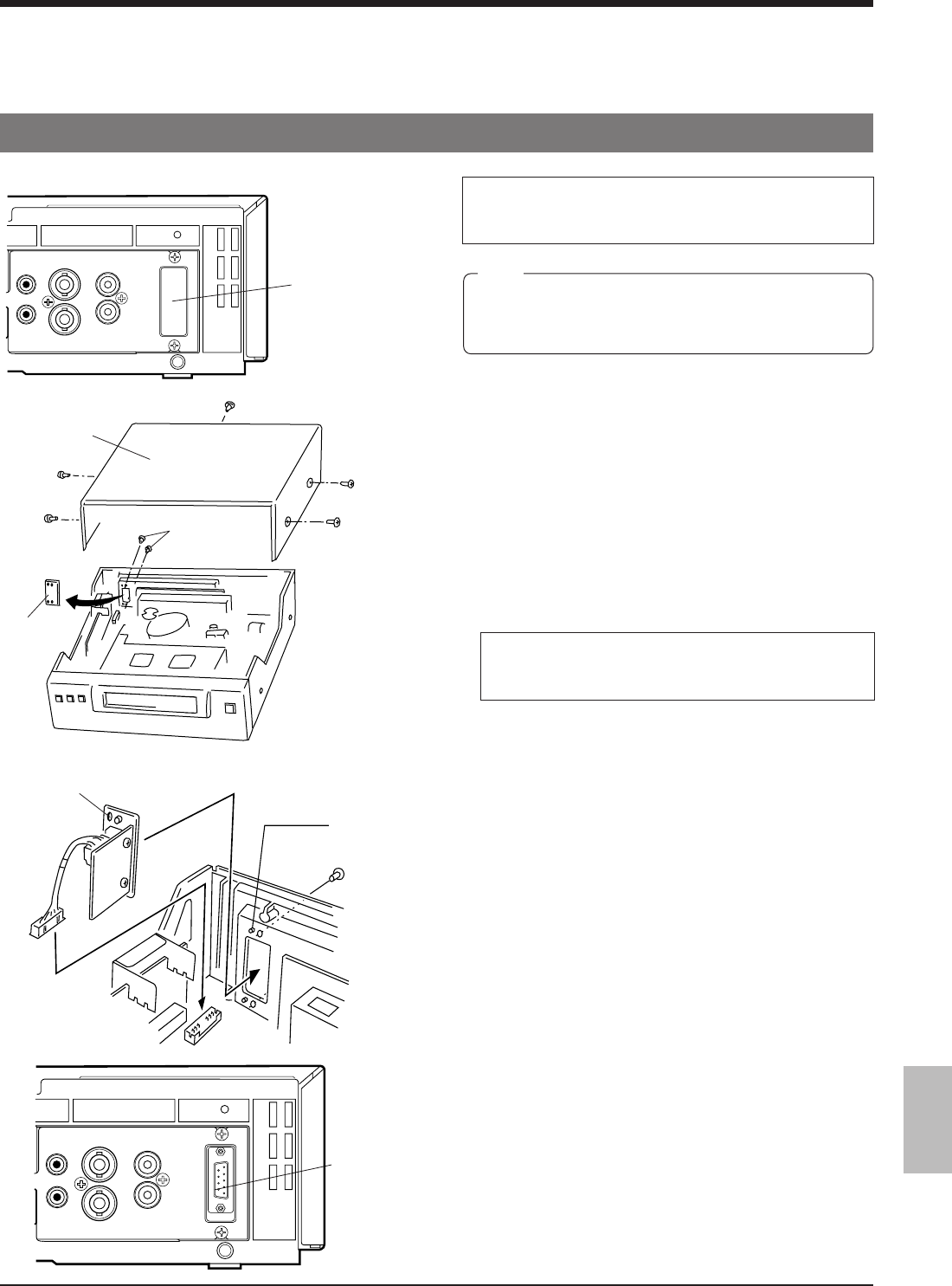
10. OPTIONAL SA-K97U RS-232C INTERFACE BOARD
Functions that can be controlled with front panel buttons and switches can also be controlled from a personal computer when
the optional SA-K97U RS-232C interface board is installed. Operation status can also be monitored on the computer.
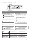
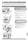
10-1. Installation of the SA-K97U
The procedure is shown below. However, to avoid
electric shock or injury, contact your local JVC
service center for details.
Projection sections
(2 positions)
Screws (2)
SA-K97U
RS-232C board
Positioning
holes
(2 positions)
Top cover
Screws
Plate
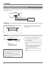
Rear panel
VIDEO
AUDIO
IN IN
OUT
OUT
REMOTE
MIC
IN
SA-K97U
installation
section
When installing this board, be careful not to injure
yourself on sharp edges and metal parts inside
the VCR.
Note:
Ⅵ Before installing the board, turn the power off and unplug
the power cord from an AC outlet.
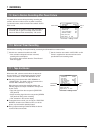
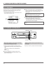
1. Detach the top cover.
Remove the 5 screws securing the top cover and lift it off.
2. Detach the plate in the VCR.
Remove the 2 screws on the rear panel. Detach the plate
from the inside of the VCR.
3. Connect the SA-K97U’s connector to the VCR.
Insert the SA-K97U connector into the connector (CN607)
on the board in the VCR using a tool such as a pincette.
• During insertion, make sure the connector is aligned
properly.
• Press both edges of the connector to insert it securely.
4. Install the SA-K97U in the VCR.
Make sure the SA-K97U bracket is facing the correct
direction and align the positioning holes on the bracket
with the projections (2 positions) on the VCR’s case.
Secure the bracket with the 2 screws removed in step 2.
5. Attach the top cover as before.
Attach the top cover to the VCR using the 5 screws
removed in step 1.
Make sure you use the correct screws.
1.
2.
3.
4.
VIDEO
AUDIO
IN IN
OUT
OUT
REMOTE
MIC
IN
SA-K97U