


Filename [SR-MV45_55U_05Name.fm]
Masterpage:Left+
12 EN
Page 12 January 10, 2007 1:18 pm
INDEX
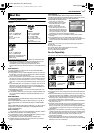
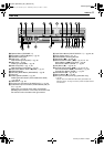
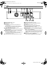
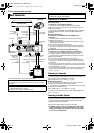
Rear View
A Region Number Label ੬ pg. 8
B AC Power Cord
੬ pg. 16
C Cooling Fan
● This prevents the temperature from rising inside the unit.
Do not remove it.
● Install the unit so as not to block the area around the fan.
● The cooling fan may be activated even if the unit is turned off
when “POWER SAVE” is set to “OFF” (੬ pg. 59).
D Digital Audio Output Connectors
[DIGITAL AUDIO OUT (COAXIAL/OPTICAL)] (DVD deck
only) ੬ pg. 54, 57
E Component Video Output Connectors [COMPONENT
VIDEO OUT (Y/P
B
/P
R
)] ੬ pg. 16
● This component video output enables you to watch the images on
the VCR deck in Progressive scan mode, refer to “VHS
Progressive Scan” (੬ pg. 35).
F S-video Output Connector (DVD deck only) ੬ pg. 16
G S-video Input Connector
੬ pg. 53
H BNC Video Output Connector [VIDEO OUTPUT]
੬ pg. 16
I S-video Output Connector
੬ pg. 16
J Video/Audio Output Connectors [VIDEO/AUDIO
OUTPUT] (DVD deck only)
੬ pg. 16
K Video/Audio Input Connectors (VIDEO/AUDIO INPUT
(L-1)) ੬ pg. 53
L Serial Command Connector (D-SUB 9-PIN) [SERIAL
COM.] ੬ pg. 73 (SR-MV55U)
● Use this connector when controlling this unit via a computer. The
cable to be used should be a RS-232C interface cable (straight
type). For details on the RS-232C interface command, refer to
page 73.
M Audio Output Connectors [AUDIO OUTPUT] ੬ pg. 16
N Remote In Connector* (REMOTE IN)
* There is currently no compatible remote control unit available.
OUTPUT
OUTPUT
DVD DVD/VCR
DVD/VCR
INPUT L-1
OPTICAL
DVD
L
R
DIGITAL
AUDIO OUT
COMPONENT
VIDEO OUT
VIDEO
AUDIO
VIDEO
AUDIO
PCM/
STREAM
L
R
VIDEO
L
R
COAXIAL
SERIAL
COM.
Y
P
B
PR
AUDIO
REMOTE IN
AEFDB
G
C
N
H I
LMJK
SR-MV45_55US.book Page 12 Wednesday, January 10, 2007 1:18 PM