Filename [SR-MV45_55U_05Name.fm]
Masterpage:Left0
16 EN
Page 16 January 10, 2007 1:18 pm
INSTALLING YOUR NEW UNIT
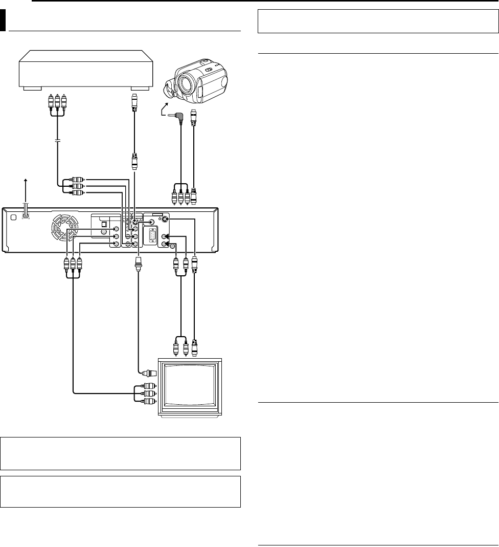
It’s essential that your unit be properly connected.
Connecting to a TV Monitor
Connect the unit to a TV depending on the TV and cables you use.
8 AV Connection
To connect to a TV with BNC connector —
A Connect an optional audio cable between the [AUDIO
OUTPUT] connectors on the rear panel of the unit and the TV’s
audio input connectors.
B Connect an optional BNC video cable between the unit’s BNC
[VIDEO OUTPUT] connector and the TV’s BNC VIDEO input
connector.
8 S-Video Connection
To connect to TV’s S-VIDEO input and AUDIO input
connectors —
A Connect the unit’s S-VIDEO output connector to the TV’s
S-VIDEO input connector.
B Connect the unit’s [AUDIO OUTPUT] connectors to the TV’s
AUDIO input connectors.
● You can obtain high-quality S-VHS pictures.
● If your TV is not stereo-capable, use the unit’s [AUDIO OUTPUT]
connectors to connect to an audio amplifier for Hi-Fi stereo sound
reproduction.
8 Component Video Connection (DVD deck only)
To connect to TV’s component video input connectors —
A Connect the unit’s [COMPONENT VIDEO OUT (Y/P
B
/P
R
)]
connectors to the TV’s component video input connectors.
B Connect the unit’s [AUDIO OUTPUT] connectors to the TV’s
AUDIO input connectors.
● You can obtain high-quality component video pictures.
● If your TV is not stereo-capable, use the unit’s [AUDIO OUTPUT]
connectors to connect to an audio amplifier for Hi-Fi stereo sound
reproduction.
● By using the component video connection, you can view the images
in the progressive mode. For switching to the progressive mode, refer
to “Scan Mode Set” (੬ pg. 65).
● You can also watch the images on the VCR deck in Progressive scan
mode via the component video output, refer to “VHS Progressive
Scan” (੬ pg. 35).
Connecting to a Camcorder
8 AV Connection
A Connect the unit’s [VIDEO/AUDIO (L/R) IN F-1] connectors on
the front panel to the camcorder’s AV connector.
● Set “FRONT AUX F-1” to “VIDEO”. (੬ pg. 59)
8 S-Video Connection
A Connect the unit’s [S-VIDEO IN F-1] connector on the front
panel to the camcorder’s s-video output connector.
B Connect the unit’s [AUDIO IN F-1] connectors on the front panel
to the camcorder’s AV connector.
● Set “FRONT AUX F-1” to “S-VIDEO”. (੬ pg. 59)
To connect to a DV camcorder, refer to “DV Dubbing (DVD Deck
Only)” (੬ pg. 51).
Connecting to Another Recorder
A Connect the unit’s [S-VIDEO INPUT] or [VIDEO INPUT]
connector to another recorder’s s-video or video output connector.
B Connect the unit’s [AUDIO INPUT] connectors to another
recorder’s audio output connectors.
Plug the end of the AC power cord into an AC outlet.
●“LOADING” blinks on the front display panel when the AC
plug of the AC power cord is connected into an AC outlet.
It takes approximately 50 seconds for the unit to be turned
on. This is not a malfunction.
Basic Connection
TTENTION:
Connect the AC plug only after all connections to the TV has been
completed.
● Make sure the package contains all of the accessories listed in
“SPECIFICATIONS” on page 86.
● Place the unit on a stable, horizontal surface.
TV
Audio/Video
cable
(not supplied)
S-video cable
(not supplied)
To [S-V ID EO
IN F-1]
To
S-VIDEO
output
S-video cable
(supplied)
To
[AUDIO
OUTPUT]
Audio cable
(supplied)
Component video
cable
(not supplied)
To
[VIDEO
OUTPUT]
Back of unit
To
[COMPONENT
VIDEO OUT
(Y/P
B
/P
R
)]
To [AUDIO/VIDEO
INPUT]
AC power cord
AC outlet
Audio/Video
cable
(not supplied)
S-video cable
(not supplied)
Camcorder
Another Recorder
BNC video
cable
(not supplied)
To S-VIDEO
input
THESE STEPS MUST BE COMPLETED BEFORE ANY VIDEO
OPERATION CAN BE PERFORMED.
SR-MV45_55US.book Page 16 Wednesday, January 10, 2007 1:18 PM


