


15
3. INSTALLATION
Please follow the instructions and the diagram below to set up the system.
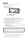
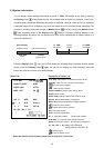
3.1 Basic Connection
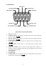
CONNECTIONG TO THE AC ADAPTER
Connect the provided AC adapter to the main unit.
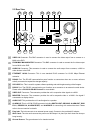
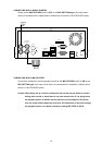
SD Card
RS-232
ALARM
DC12V
AUDIO
IN
IN
OUT
OUT
VIDEO
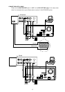
TO
MONITOR
TO
MUX'S VCR IN
FROM MUX
MAIN MONITOR
I/O
RS-485
ETHERNET
10/100
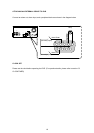
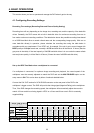
DC IN terminal
DC cord
Provided AC adapter
(model:STD-1205)
Provided AC
mains cable
AC
Clamp
Screw
1. Connect the DC cord of the AC adapter to the DC IN terminal of the main unit.
2. To prevent accidental disconnection of the DC cord, fasten the DC cord with a wire catch.
1) Remove 1 screw followed by the wire catch.
2) Insert the DC cord into the wire catch and fasten the wire catch unto the main unit.
3. Connect the provided power cord to the AC IN terminal of the AC adapter.
4. Connect the power cord to the power socket.
• Power is channeled into the unit and the OPERATE indicator lights up green.
(OPERATE ON mode)
• Press OPERATE button
for at least 3 seconds to power off and the OPERATE indicator lights
up orange.. (OPERATE OFF mode)
The orange light signals the hard-disk drive is power stand by.
Memo
• Even in the OPERATE OFF mode, a small amount of electricity will still flow into the unit.
• When the unit is in the OPERATE OFF mode, no operation can be performed except that of the
OPERATE button.
Note:
• Please supply power to the unit via the provided AC adapter. Do not use other power sources.
• During recording or playback, please do not unplug the DC or power cord.
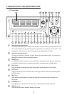
* About the location of the buttons, please refer to Page 10 2.1 Front View.