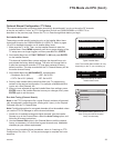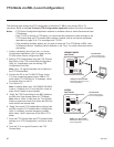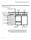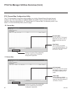
47
206-4200
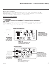
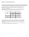
Remote Jack Pack / TV Connections & Setup
COMPONENT
IN
RS-232C IN
(SERVICE ONLY)
UPDATE
RESET
AUDIO IN
(RGB/DVI)
.....
....
RL
P
B
Y P
R
1
HDMI/DVI IN
OPTICAL
DIGITAL
INTERFACE
VIDEO
L/MONO-AUDIO-R
AV IN 1
RGB IN (PC)
.....
.....
.....
LAN2
TV-LINK CFG
GAME CONTROL
/MPI
..........
AUDIO OUT
SERVICE
ONLY
SPEAKER
OUT
(8 )
LAN1
RJP
ANTENNA IN
HDMI/DVI IN 1
Connect HDMI
connector from
RJP cable bundle.
AUDIO/VIDEO IN 1
Connect Composite Video/
Audio connectors from RJP
cable bundle. (Composite
Video on legacy RJP only.)
RJP INTERFACE
Connect RJ-45
Control cable from
RJP cable bundle.
COMPONENT
IN
RS-232C IN
(SERVICE ONLY)
UPDATE
RESET
AUDIO IN
(RGB/DVI)
.....
....
RL
P
B
Y P
R
..........
2
1
HDMI/DVI IN
OPTICAL
DIGITAL
RJP
INTERFACE
VIDEO
L/MONO-AUDIO-R
AV IN 1
RGB IN (PC)
.....
.....
.....
LAN2
TV-LINK CFG
GAME
CONTROL/MPI
..........
AUDIO OUT
SERVICE
ONLY
SPEAKER
OUT
8
LAN1
HDMI/DVI IN 1
Connect HDMI
connector from
RJP cable bundle.
RJP INTERFACE
Connect RJ-45
Control cable from
RJP cable bundle.
RGB IN (PC)
Connect RGB connector from RJP
cable bundle (legacy RJP only).
AUDIO/VIDEO IN 1
Connect Composite Video/
Audio connectors from RJP
cable bundle. (Composite
Video on legacy RJP only.)
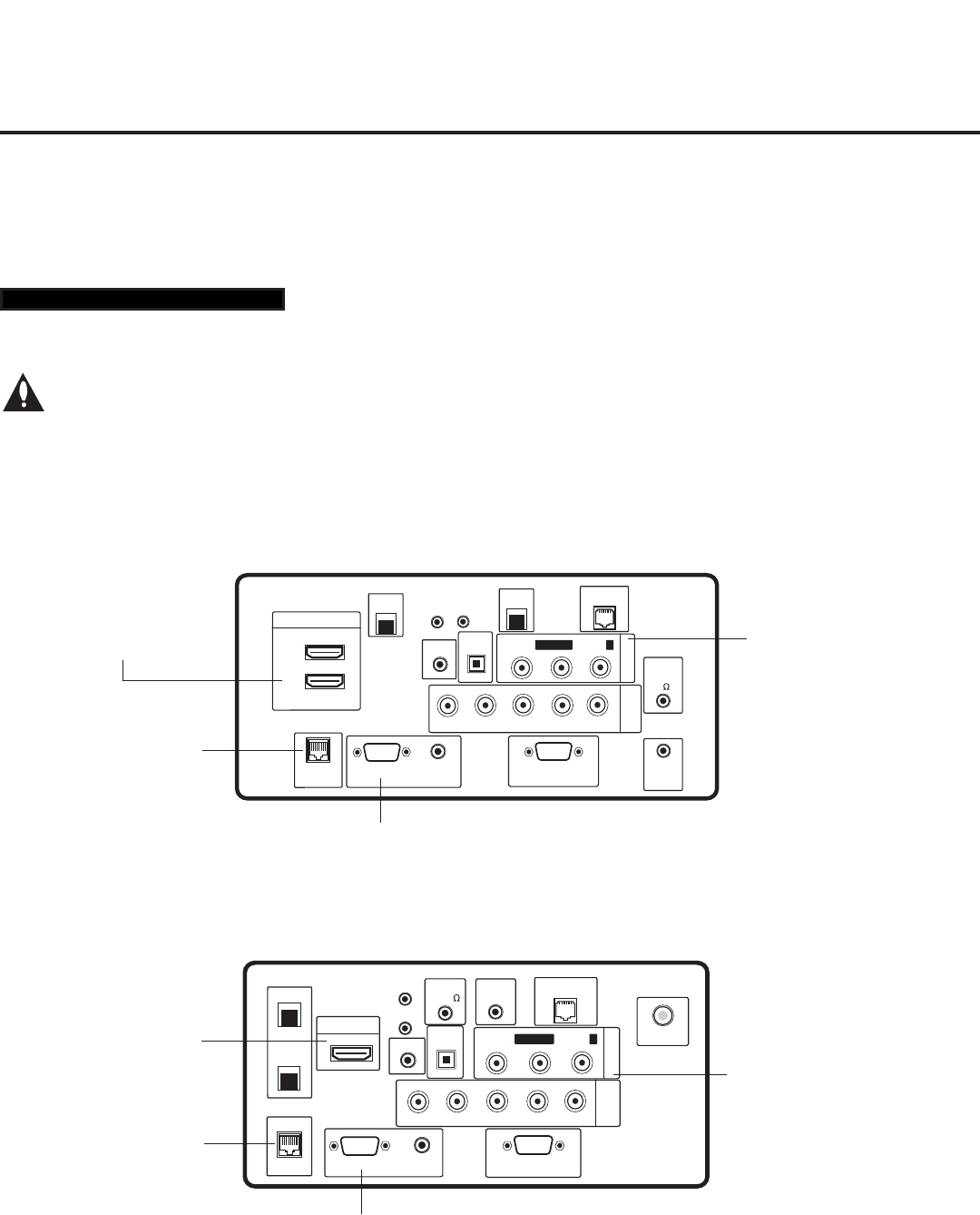
LD660H/LD665H Jack Panel
LV555H Jack Panel
Remote Jack Pack Setup
RJP Available? If you will use a Remote Jack Pack (RJP) in your system, set Installer Menu item 093
RJP AVAILABLE appropriately (for example, on a legacy model RJP: HDMI Mode, set RJP AVAILABLE
to 001). See Installer Menu detailed descriptions for further information.
TV Connections
Make these connections ONLY after Master TV Setup and TV cloning procedures are
complete.
Refer to the appropriate figure below, and connect the RJ-45 Control cable from the RJP cable bundle to
the RJP INTERFACE port on the TV’s jack panel. Then, connect HDMI, RGB, and Composite Video/
Audio connectors, as applicable, for the cable bundle.
093 RJP AVAILABLE 001
RGB IN (PC)
Connect RGB connector from RJP
cable bundle (legacy RJP only).


