


35 960-Hour Time Lapse Video Cassette Recorder 960-Hour Time Lapse Video Cassette Recorder 4
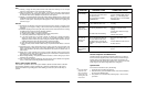
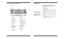
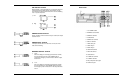
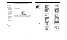
Back Panel
1 AC POWER CORD
2 WARNING OUT terminal
3 SERIES IN terminal
4 COM terminal
5 SERIES OUT terminal
6 SW OUT terminal
7 VIDEO OUT jack
8 VIDEO IN jack
9 AUDIO IN jack
10 TAPE END terminal
11 PANIC IN terminal
12 COM terminal
13 ALARM OUT terminal
14 ALARM IN terminal
15 MIC (microphone input) jack
16 AUDIO OUT jack
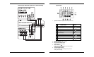
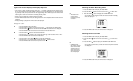
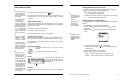
SW OUTPUT Terminal
While recording, a pulse signal(DC 5V) is output at the SW OUT
terminal after each recording period. This terminal is usually
connected to the switch input of devices like a camera switching
unit, or a quad compressor.
1) Low
2) High
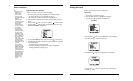
SERIES OUTPUT Terminal
During recording, when the end of the tape is reached, the output
becomes DC 5V .
SERIES INPUT Terminal
If the input becomes DC 5V for 200 msec or more, the VCR
starts series recording.
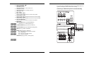
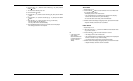
WARNING OUTPUT Terminal
1) “High”
If the error display on the display panel continues to flash,
the output becomes DC 5V. If the POWER button is
pressed, the emergency mode is released. then the output
becomes 0V.
2) “Low”
If the error display on the display panel continues to flash,
the output becomes 0V. If the POWER button is pressed,
the emergency mode is released. then the output becomes
DC 5V.