


10
SDR24/96
SDR 24/96
IN OUT
WORD CLOCK I/O
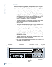
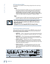
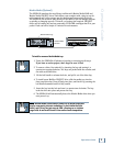
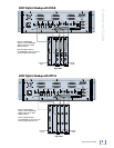
The following is the recommended setup for establishing proper sample clock
synchronization with the devices connected to the SDR24/96.
ADAT Optical
With the SDR24/96 as a master, set the receiving device(s) to derive sample
clock from their ADAT optical ports if the ports are self-clocking. In this
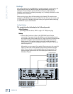
case, no word clock connection is necessary. If the ADAT optical ports on the
receiving devices are not self-clocking, connect WORD CLOCK OUT of the
SDR24/96 to Word Clock In on the receiving device(s). If the receiving device
is an ADAT multitrack recorder, use ADAT SYNC OUT of the SDR24/96 to
the SYNC IN on the ADAT.
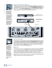
With the SDR24/96 configured as a slave, there is no need to connect the
word clock connection on the SDR24/96 (the SDR can derive its word clock
from the Digital Optical input). Make sure the sample clock
(SETUP:Sync:SClk) is set to ADAT A, ADAT B, or ADAT C (whichever is the
master ADAT).
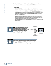
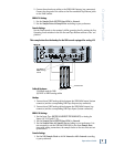
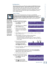
Word clock
input jack
BNC-Tee
adaptor
Word Clock to
other Slaves
Word Clock
From Master
Note:Note:
Note:Note:
Note: Use 75 W coaxial cables when con-
necting word clock to the Word Clock
input jack. If there are more devices to con-
nect to the Word Clock, use a BNC Tee
adapter to feed the signal on to the next
device in the chain.
Note:Note:
Note:Note:
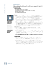
Note: If you are using an SDR24/96 with the Mackie Digital
8•Bus console, you may need to turn on the Digital 8•Bus first.
The Apogee Clock I/O on the D8B prefers not to see an active
signal at its Word Clock input when it powers up.