


16
SDR24/96
SDR 24/96
OUT
IN
IN
IN
OUT
OUT
DIGITAL WORD CLOCK I/O MIDI
ADAT SYNC
IN
ADAT SYNC
OUT
SERIAL
9-PIN
FOOT
SWITCH
SMPTE
MICRO/
REMOTE 24
CNTRL
ANALOG OUT 1 - 8 ANALOG OUT 9 - 16 ANALOG OUT 17 - 24
ANALOG IN 1 - 8 ANALOG IN 9 - 16 ANALOG IN 17 - 24
RISK OF ELECTRIC SHOCK
DO NOT OPEN
REPLACE WITH THE SAME TYPE FUSE AND RATING.
DISCONNECT SUPPLY CORD BEFORE CHANGING FUSE
UTILISE UN FUSIBLE DE RECHANGE DE MÊME TYPE.
DEBRANCHER AVANT DE REMPLACER LE FUSIBLE
WARNING:
TO REDUCE THE RISK OF FIRE OR ELECTRIC SHOCK, DO NOT
EXPOSE THIS EQUIPMENT TO RAIN OR MOISTURE. DO NOT REMOVE COVER.
NO USER SERVICEABLE PARTS INSIDE. REFER SERVICING TO QUALIFIED PERSONNEL.
CAUTION
SERIAL NUMBER
MANUFACTURING DATE
AVI S:
RISQUE DE CHOC ELECTRIQUE — NE PAS OUVRIR
CONCEIVED, DESIGNED, AND MANUFACTURED BY MACKIE DESIGNS INC • WOODINVILLE • WA 98072 • USA
MADE IN USA • FABRIQUE AU USA • PATENTS PENDING COPYRIGHT ©1998 THE FOLLOWING ARE TRADEMARKS OR
REGISTERED TRADEMARKS OF MACKIE DESIGNS INC.: "MACKIE.", MACKIE DIGITAL SYSTEMS AND THE "RUNNING MAN" FIGURE.
POWER
USB
1 - 8
IN OUT
DIGITAL
9 - 16
IN OUT
DIGITAL
17 - 24
X2
1-4
X2
5-8
X2
9-12
IN OUT
24 TRACK/24 BIT DIGITAL
AUDIO RECORDER
HIGH RESOLUTION
NON-LINEAR RECORDER
96
SDR
100 - 240V 250mA
50/60Hz
FOOT
SWITCH
TO HDR
REMOTE JACK
REMOTE 24
MICRO REMOTE
DO NOT PLUG INTO
ETHERNET
WARNING
TO SDR REMOTE JACK
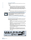
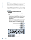
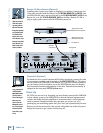
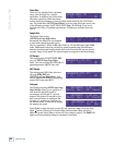
Remote 24/Micro Remote (Optional)
Installing either remote is as simple as plugging in a telephone. Connect one end
of the cable (supplied with the Remote) to the MICRO/REMOTE 24 CNTRL jack
on SDR24/96 rear panel, and the other end to the TO HDR REMOTE JACK on the
Remote 24, or to the TO SDR REMOTE JACK on the Micro Remote. It’s OK to
plug or unplug either remote with the SDR24/96 powered on.
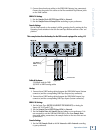
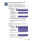
Footswitch (Optional)
For hands-free do-it-yourself punches and Play/Stop operations, connect the cable
of a momentary, normally open footswitch to the FOOT SWITCH 1/4" TS jack on
the rear panel of the SDR24/96 or the Remote 24. If you have a Remote installed
you can connect two foot switches, one to the SDR24/96 and one to the Remote.
Each footswitch functions independently of the other. Footswitch functionality is
assigned in the front panel SETUP:System menu.
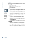
Power-Up
OK, NOW you can turn it on. Assuming you have already connected the SDR24/96
to your console, power up the SDR24/96 first, then the outboard equipment and
console, and finally the power amplifiers or powered monitors. Audio equipment
tends to generate unexpected clicks and pops when you power it up, so by
powering up your monitoring system last, you’ll save your speakers and your ears.
Before you read the next section, take a quick, self-guided tour of the front panel
display and controls to get a sense of where they are.
Note:Note:
Note:Note:
Note: The Remotes
duplicate nearly all
of the front panel
operating controls.
When we describe a
front panel operation,
you’ll probably find
it available on the
Remote also. If you
have a Remote, try it
both ways. If you don’t
have a Remote yet,
think of how conve-
nient it would be.
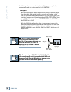
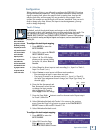
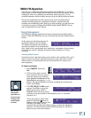
Remote
connection
Footswitch
Back panel of the
Mackie Remote 24
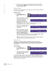
Footswitch
Note:Note:
Note:Note:
Note: If you are
using an SDR24/96
with the Mackie
Digital 8•Bus console,
you may need to
turn on the Digital
8•Bus first. The
Clock I/O on the
D8B prefers not to
see an active signal
at its Word Clock
input when it pow-
ers up.
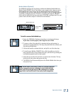
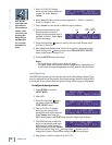
Back panel of the
Mackie Micro Remote