


14
SDR24/96
SDR 24/96
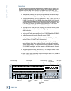
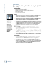
Digital Hookup
This example describes the hookup for the D8B console equipped for digital I/O
(DIO•8 or OPT•8).
Cables & Hardware
(3) DIO•8 or OPT•8 cards for D8B
(1) Apogee Clock I/O card for D8B (if D8B is the slave)
(6) ADAT optical cables
(1) 75Ω BNC word clock cable
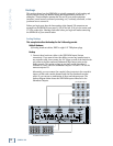
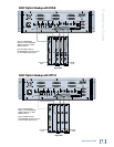
Hookup
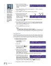
1. Connect three ADAT optical cables from the SDR24/96 DIGITAL optical
outputs to the optical inputs on the corresponding D8B I/O cards.
2. Connect three ADAT optical cables from the SDR24/96 DIGITAL optical
inputs to the optical outputs on the corresponding D8B I/O cards.
3. When the D8B is the clock master, the SDR24/96 can derive its clock from
the Digital Optical input. When the SDR24/96 is the clock master, connect
the WORD CLOCK OUT on the SDR24/96 to the WORD CLOCK IN on
the D8B (the D8B must have an Apogee Clock I/O card installed).
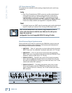
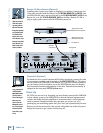
SDR24/96 Settings
1. Set the Input Type (SETUP:I/O:INPUT TYPE SELECT) to ADAT for
Inputs 1-8, 9-16, and 17-24.
2. If the SDR24/96 is the clock master, set the Sample Clock to Internal. If
the SDR24/96 is a clock slave, set the Sample Clock to ADAT A (or B or C).
(SETUP:Sync:SClk:ADAT A).
3. Set the Sample Rate to 44.1 kHz or 48 kHz according to your preference.
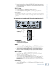
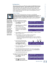
Console Settings
1. If you have DIO•8 cards installed, set the Tape Input and Tape Output
format for each card to ADAT. OPT
•8 cards need no configuration.
2. If the D8B is the clock master, set the Sample Clock to either 44.1 k
Internal or 48 k Internal. If it is a clock slave, then set the Sample Clock
to either 44.1 kHz or 48 kHz to match the Sample Rate selected on the
SDR24/96. Set the Apogee Clock to Word Clock.
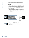
Note: If you are us-
ing a D8B console
with OPT•8 cards
installed and the
SDR24/96 is the
clock master, then a
Clock I/O card must
also be installed in
the D8B to properly
synchronize its word
clock with the
SDR24/96.