


L
R
S-VIDEO
VIDEO
HDMI
S-VIDEO
R
L
Y
Pb
Pr
VIDEO
R
L
Y
P
b
Pr
Pr
VI
D
E
O
R
L
AC IN
HDMI
S-VIDEO
R
L
Y
Pb
Pr
VIDEO
R
L
Y
Pb
VIDEO
R
L
AC IN
L
R
S
-
VI
D
E
O
VI
D
E
O
L
R
S
S
VI
E
O
VI
D
E
E
O
O
O
35
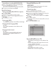
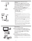
Connect Accessory Devices
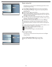
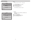
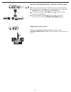
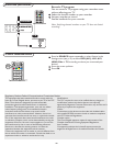
Recorder (VCR-DVD+RW)
Note: Do not place your recorder too close to the TV screen. Some
recorders may be susceptible for signals from the display. Keep recorders
a minimum distance of 20” from the screen.
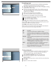
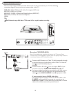
There is a wide range of audio and video devices that can be connected to your TV. The following
connection diagrams show you how to connect them to the TV.
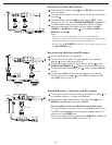
DVD (AV1)
YPbPr, VIDEO and L/R Audio, (For integrated DVD only)
AV2 YPbPr, VIDEO and L/R Audio,
AV3 VIDEO, S-VIDEO, L/R Audio and Digital Audio out (SPDIF OUT)
Side VIDEO, S-VIDEO, L/R Audio and Headphone
.
HDMI
75
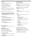
Don’t insert any cable here. This area is for repair center use only.
Connect the RF Antenna or Cable TV cable (eventually through
an optional two-way signal splitter and/or Cable TV converter
box) to the RF IN socket of your
recorder.
Connect another RF cable from the output OUT of your
recorder to the TV’s CABLE/ANTENNA 75 jack.
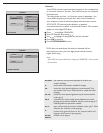
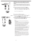
For
better playback quality for stereo device only, also connect
the Video, Audio Left and Right (only for stereo devices) AV
cables to the VIDEO, AUDIO L and R input jacks of AV3.
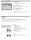
If your recorder has an S-VHS video jack:
For improved picture quality, connect an S-video cable to the
S-VIDEO input instead of connecting the recorder to the
VIDEO jack of AV3. S-Video does not provide audio, so audio
cables must still be connected to provide sound.
OUT
AV3:
L + R + VIDE
O
HDMI
Pb
Y
Pr
VIDEO
R
L
Y
Y
P
P
b
Pr
VIDE
O
R
L
S-VIDEO
R
L
3
CABL
E
IN OUT
2
ANTENNA
1
2
3