


User Guide 7MicroTrack II
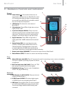
3 - Hardware Controls and Indicators
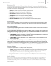
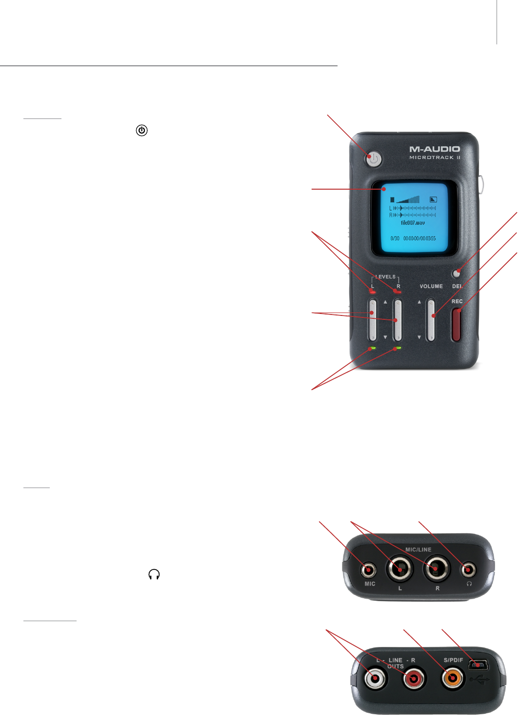
Front
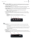
1. Power Button
: Press and hold this button for
approximately one second to turn MicroTrack II on and
off. Pressing and holding this button for approximately
ten seconds forces MicroTrack II to shutdown, should
the unit ever become unresponsive
2. LCD Display: This shows the current status of
MicroTrack II.
3. Clip Indicators: These LEDs will light when an input
signal exceeds -1dB.
4. Input Levels Adjust (LEVELS): These control the
individual recording levels of the MicroTrack II left and
right inputs. The current input level is represented by
triangles in the L/R level meters on the main screen.
5. Signal Indicators: These LEDs will light when a
signal greater than -40dB is detected at the selected
input.
6. Delete Button (DEL): In normal player/recorder
operation, the delete button deletes the current (or
selected) audio file. The delete button is also used
to stop the MicroTrack II USB drive mode (known as
“host mode”) and return to normal player/recorder functionality.
7. Output Level Adjust (VOLUME): This controls the output volume of MicroTrack II.
8. Record Button (REC): This button is used to start and stop recordings.
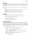
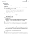
Top
9. Stereo Mic Input Jack (MIC): This 1/8” stereo jack is used for connecting a mono or stereo microphone.
This input is capable of providing 5V power for electret
microphones.
10. Mic/Line Input Jacks (MIC/LINE): These 1/4” TRS
jacks accept microphone and line-level signals.
11. Headphone Jack
: Connect a pair of headphones
with an 1/8” plug for monitoring.
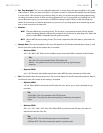
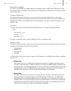
Bottom
12. RCA Outputs (L-LINE-R OUTS): These are line-level
outputs from MicroTrack II.
13. S/PDIF Input (S/PDIF): This allows digital signals
in S/PDIF format to be recorded by MicroTrack II.
14. USB Input: Connect MicroTrack II to a host computer
or to the included USB power supply using this input.
This will also charge the MicroTrack II battery when
connected.