


48
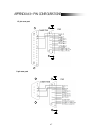
PIN 3, 4, 5, 6 ALARM INPUT
To connect wire from ALARM INPUT (PIN 3, 4, 5, 6) to GND ( PIN 9 ) connector, DVR will start recording and
buzzer will be on. When alarm has been triggered, signal becomes “Low”, and it will stop all alarm activities.
Under normal operation, signal remains “High”.
PIN 7. EXTERNAL ALARM NC
Under normal operation COM connects with NC and disconnects with NO. But when alarm is triggered, COM
disconnect with NC, and connect with NO.
PIN 8. EXTERNAL ALARM NO
Under normal operation, COM will disconnect from NO. But when Alarm is triggered, COM will connect with NO.
PIN 9. GND
GROUND
PIN 12. DISK FULL (OUTPUT)
When the HDD is full, it sends a signal to trigger next DVR recording mode, if you install another DVR. Under
normal operation, the signal remains “High”, but when the disk is full, DVR will send “Low” signal.
PIN 14. ALARM RESET (INPUT)
To connect wire from ALARM RESET ( PIN 14 ) to GND ( PIN 9 ) connector, it can disable ALARM. An external
signal to ALARM RESET ( PIN 14 ) can be used to reset both ALARMOUTPUT signal and DVR’s internal buzzer.
When alarm has been triggered, signal becomes “Low”, and it will stop all alarm activities. Under normal operation,
signal remains “High”.
PIN 15. EXTERNAL ALARM COM
Under normal operation COM connect with NC and disconnect with NO. But when alarm is triggered, COM
disconnects with NC, and connects with NO.