


24
24
Part II: Installation
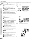
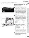
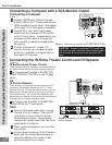
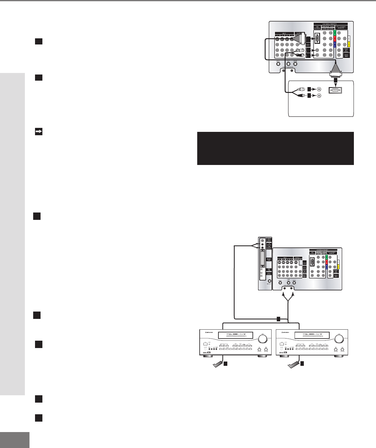
Figure 1. Connecting a computer with a VGA monitor output.
AUDIO
VGA OUTPUT
L
R
VGA MONITOR
CABLE
VGA MONITOR
CABLE
White
Red
1
2
2
2
2
1
TV back panel
Computer with VGA Monitor Output.
Connecting a Computer with a VGA Monitor Output
Connecting a Computer
(Figure 1)
1
Connect VGA Monitor Out from the com-
puter to VGA on the TV back panel using a
VGA compatible monitor cable. See Appen-
dix B, page 73, for VGA signal compatibility.
2
Connect the L (left) and R (right) audio
cables from the computer to VGA AUDIO
on the TV back panel. In cases where your
computer’s audio output is a single mini-
jack, a splitter is needed to complete this
connection.
To utilize the bene ts of a digi tal A/V
receiver, connect your computer’s digital
audio out, if available, to a digital input on
your digital A/V receiver.
TV back panel
A/V Receiver
D IG ITAL
SURROUND
S
CH
Other A/V Device
D IG ITAL
SURROUND
S
CH
AND/OR
1
2
2
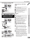
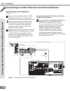
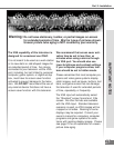
Figure 2. Connecting the IR Home Theater Control
and/or Repeater.
IR Emitter-Home Theater Control
These emitters are not IR repeaters, but instead used by
the NetCommand feature to control supported devices.
1
a: Connect the IR emitter to IR EMITTER-
HOME THEATER CONTROL on the TV back
panel.
OR
IR Emitter-Repeater
These emitters are not used by NetCommand, but will
repeat any IR command received by the TV. These
emitters allow the TV to be the remote control sensor for
other devices that are outside of the range of the hand-
held remote control. Do not use these repeaters with
devices that can receive the remote control signal directly,
as the signals can interfere with each other.
1
b: Connect the IR emitter to IR EMITTER-
REPEATER on the TV back panel.
THEN
2
Place the IR emitter cable under or along
the side of the A/V device. Place the IR
lens directly in front of the A/V device’s
infrared signal receiver. Infrared signal
receivers are usually behind the front trans-
lucent panel of the device.
3
Place unused transmitters in an out-of-the-
way location.
4
For permanent installation of the IR emitter
cable, use the included adhesive tape to
secure the bottom of the emitter to the
anchoring object of your choice.
Connecting the IR-Home Theater Control and IR Repeater
(Figure 2)
Connecting a Computer and the IR Home Theater Control and Repeater
CAUTION: To assure continued FCC compliance,
the user must use a shielded video interface cable
with bounded ferrite cores, when using the VGA
input.