


18
18
ANT-A
S-VIDEO
L
(MONO)
R
ANT -B
CABLE
LOOP-OUT
INPUT INPUT OUTPUT
FIXED/
VARIABLE
2
1
VHF/UHF
(75 OHMS)
V
I
D
E
O
A
U
D
I
O
TUNER/
MONITOR
L
R
Y
Cb
DVD
(YCrCb)
AUDIO
Cr
COMPONENT
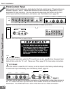
IR EMITTER HOME THEATER
AV Receiver (M-VR900)
Back panel section
Attach
only
one
cable
type
1
1
23
W
h
i
t
e
White
R
e
d
Red
TV back panel
ANT-A
IR EMITTER HOME THEATER
S-VIDEO
COMPONENT
L
(MONO)
R
ANT -B
CABLE
LOOP-OUT
INPUT INPUT OUTPUT
FIXED/
VARIABLE
2
1
VHF/UHF
(75 OHMS)
V
I
D
E
O
A
U
D
I
O
TUNER/
MONITOR
L
R
Y
Cb
DVD
(YCrCb)
AUDIO
Cr
Red
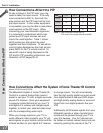
Audio system back panel section
OUTOUT
OUT
ININININ
SUBWOOFER
(MONO)
CD
AUX TAPE
1
TAPE
2
L
R
TV back panel
White
White
1
Red
Please see your A/V receiver Owner’s
Guide for more detailed connections.
Additional connection cables are not
provided with the TV. They should be
available at most electronic stores.
Part II: Installation
Connecting an Audio Receiver
Connecting an Audio Receiver
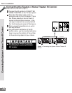
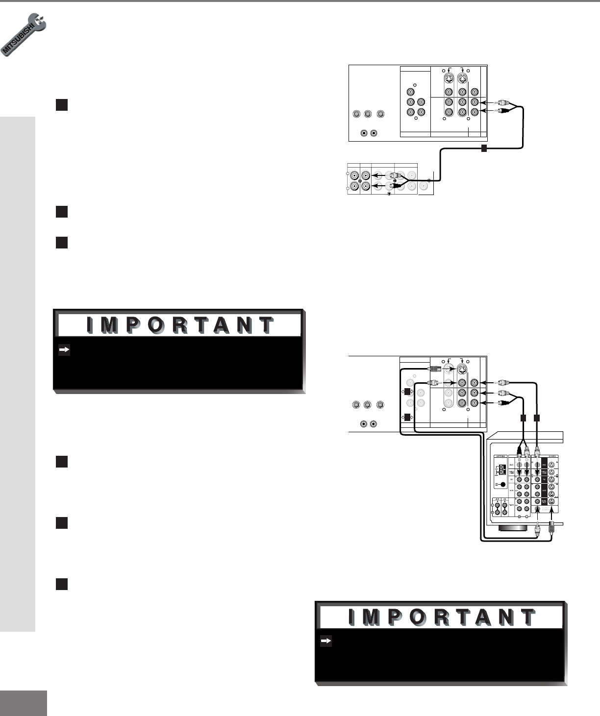
Stereo Audio System
(Figure 1)
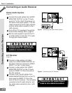
1
Connect the audio cables from AUDIO
MONITOR OUTPUT on the TV back
panel to TV IN or AUX IN terminals on
the back of the audio system. The red
cable connects to the R (right) channel,
and the white cable connects to the L
(left) channel.
2
Turn off the TV’s speakers through the
Audio/Video Settings Menu, page 41.
3
Set the audio system’s input to the TV
or AUX position to hear the TV’s audio
through your stereo system.
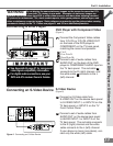
A/V Receiver
(Figure 2)
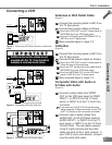
1
Connect a video cable or S-Video
cable from VIDEO MONITOR OUT on
the back of the A/V receiver to VIDEO
INPUT-1 on the TV back panel.
2
Connect a video cable from VIDEO
MONITOR OUTPUT on the TV back
panel to VIDEO TV IN on the back of
the A/V receiver.
3
Connect a set of audio cables from
AUDIO MONITOR OUTPUT on the TV
back panel to AUDIO TV IN on the
back of the A/V receiver. The red cable
connects to the R (right) channel, and
the white cable connects to the L (left)
channel.
Figure 1. Connecting the Stereo Audio System
Figure 2. Connecting the A/V Receiver.