


20
20
ANT-A
IR EMITTER HOME THEATER
S-VIDEO
COMPONENT
L
(MONO)
R
ANT -B
CABLE
LOOP-OUT
INPUT INPUT OUTPUT
FIXED/
VARIABLE
2
1
VHF/UHF
(75 OHMS)
V
I
D
E
O
A
U
D
I
O
TUNER/
MONITOR
L
R
Y
Cb
DVD
(YCrCb)
AUDIO
Cr
TV back panel
A/V Receiver
1
D IGI TA L
SU R R O U N D
S
CH
Other A/V Device
D IGI TA L
SU R R O U N D
S
CH
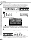
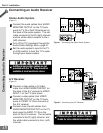
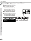
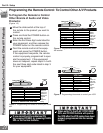
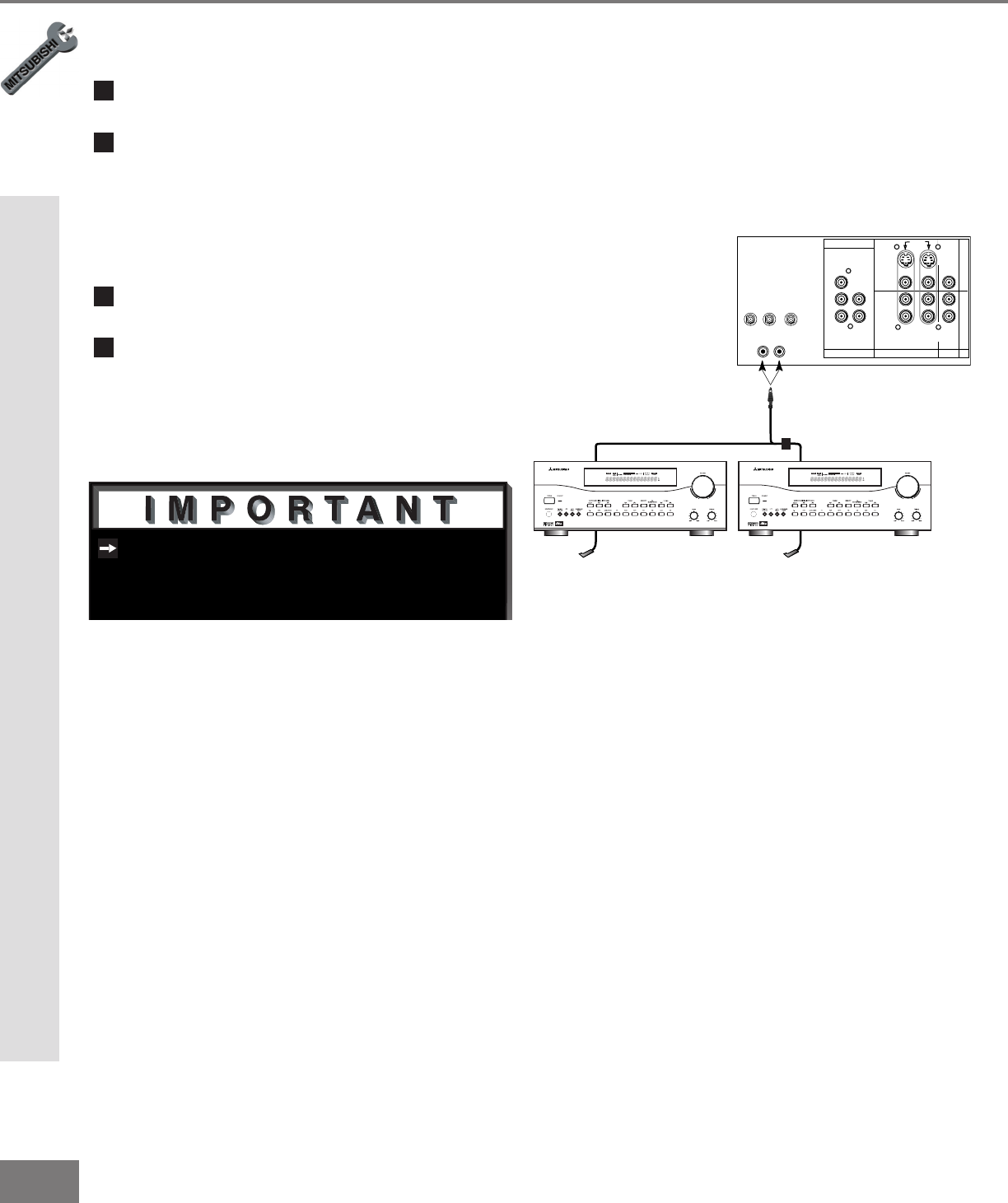
Figure 1. Connecting the System 4 Home Theater IR
Control.
See page 53 for details on using the
TV’s IR emitter to control a Mitsubishi
A/V receiver.
Part II: Installation
Connecting the System 4 Home Theater IR Control
1
Connect the IR emitter to IR EMITTER
HOME THEATER on the TV back panel.
2
Place the IR emitter cable under or
along the side of the A/V device. Place
the IR lens directly in front of the A/V
device’s infrared signal receiver. Infra-
red signal receivers are usually behind
the front translucent panel of the device.
3
Place unused transmitters in an out-of-
the-way location.
4
For permanent installation of the IR
emitter cable, use the included adhesive
tape to secure the bottom of the emitter
to the anchoring object of your choice.
Connecting the System 4 Home Theater IR Control
Models VS-60719, VS-70709. (Figure 1)