


3. SPECIFICATIONS MELSEC-A
3-10
3.5 I/O Signals to the Master Station
Assignment of the I/O signals and function of each signal are explained.
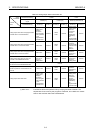
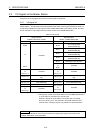
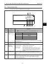
3.5.1 I/O signal list
The AJ65BT-64DAV/DAI uses 32 input points and 32 output points for exchanging signals with the
master station.*
1
The allocation of the I/O signals and the name of each signal are listed in Table 3.4.
An RX device indicates an input signal from the AJ65BT-64DAV/DAI to the master module, and a RY
device indicates an output signal from the master module to the AJ65BT-64DAV/DAI.
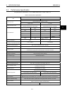
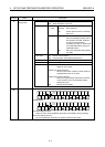
Table 3.4 I/O signals
Signal direction:
AJ65BT-64DAV/DAI→Master
Signal direction:
Master→AJ65BT-64DAV/DAI
Device No. Signal name Device No. Signal name
RXn0 RYn0
CH.1 Analog output
enable/disable flag
RYn1
CH.2 Analog output
enable/disable flag
RYn2
CH.3 Analog output
enable/disable flag
RYn3
CH.4 Analog output
enable/disable flag
to
RYn4 Offset/gain value selection
RXnF
Unusable
RYn5
to
RYnF
Unusable
RX (n+1) 0
to
RX (n+1) 7
Unusable
RY (n+1) 0
to
RY (n+1) 7
Unusable
RX (n+1) 8
Initial data processing request
flag
RY (n+1) 8
Initial data processing complete
flag
RX (n+1) 9 Initial data setting complete flag RY (n+1) 9 Initial data setting request flag
RX (n+1) A Error status flag RY (n+1) A Error reset request flag
RX (n+1) B Remote READY
RX (n+1) C
to
RX (n+3) F
Unusable
RY (n+1) B
to
RY (n+3) F
Unusable
n: The address allocated to the master station in the station number setting
*1 Although the number of occupied stations for the AJ65BT-64DAV/DAI is
2, inputs, RX(n+2) 0 to RX(n+3)F, are not used.
However, devices for inputs, RX(n+2) 0 to RX(n+3)F, and outputs,
RY(n+2) 0 to RY(n+3) F, are reserved in the master module or CPU
module. When creating a program, pay attention to device allocation.
Point
If a device not allowed to use is turned on/off from the sequence program, the function of the
AJ65BT-64DAV/DAI is not guaranteed.