


GB 27
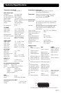
Transmission Standards
DVB, MPEG 2
LNB / Tuner input
Connector 1x F-type (LNB)
RF input frequency 950-2150 MHz
RF input power level -20 to -70 dBm
Supply voltage 13,5 /18,5 V ±5%
Max. current 400 mA, overload protected
Control voltage 22 kHz, 0,65 V
pp
DiSEqC Tone burst A/B or
Level 1, 1-4
RF impedance 75 Ω
TV SCART
Video output 1 V
pp
(±1 dB) / 75 Ω
Audio output 0,5 V
rms
/ R
L
>10 kΩ
RGB output Internal RGB or from
SATELLITE SCART
RGB bandwidth 6 MHz ±3 dB
Fast blanking output Internal RGB or from
SATELLITE SCART
Status output 0/6/12 V / R
L
10 kΩ
VIDEO SCART
Video output 1 V
pp
(±1 dB) / 75 Ω
Video input 1 V
pp
/ 75 Ω
Audio output 0,5 V
rms
/ R
L
>10 kΩ
Audio input 0,5 Vr
ms
/ R
L
>10 kΩ
Status input 0/6/12 V / R
L
>10 kΩ
SAT SCART
Video input 1 V
pp
/ 75 Ω
RGB input Yes
Fast blanking input Yes
Audio input 0,5 V
rms
/ R
L
>10 kΩ
Status input 0/6/12 V / R
L
>10 kΩ
AUDIO R L
Connector 2 x RCA (R+L)
Output 0,5 V
rms
/ R
L
10 kΩ
Low speed serial data (RS 232)
Connector 9-pin D-sub
Signals RS232, max. 19.2 kbit/s
Pin 1 not connected 2 RXD
3 TXD 4 Set to high
5 GND 6 not connected
7 RTS 8 CTS
9 not connected
SCSI
Connector 50 pol.
Signal SCSI-2 (max. 3,8 MB/s)
Control output, 0/12 VOLT
Connector 1 x RCA / Cinch
Voltage 0/12 V 50 mA
Conditional access system:
Interface for the Common Interface
CA-module (DVB Standard)
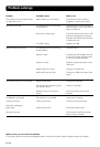
Front panel Display 8 character alphanumeric matrix,
5x7 pixels. Buttons:
,
(standby,
progr. number up and down)
General data
Article code The model code, variant and serial number,
are located on a label on the underside of
the housing.
Software Software version (V.x.xxx) and Boot version
(Bx.xx or Boot x.xx) are displayed in the
matrix display when the Mediamaster is
powered up.
Supply voltage 230 V AC ±15%, 50-60 Hz
Power consumption max 40 W
Power consumption in
standby 2 W
Working temperature +5° C to +40°
Storage temperature - 40° C to +65° C
Operating distance for
remote control max 10 meters
Dimensions (w x d x h) 380 x 240 x 65 mm
Weight 2,2 kg approx
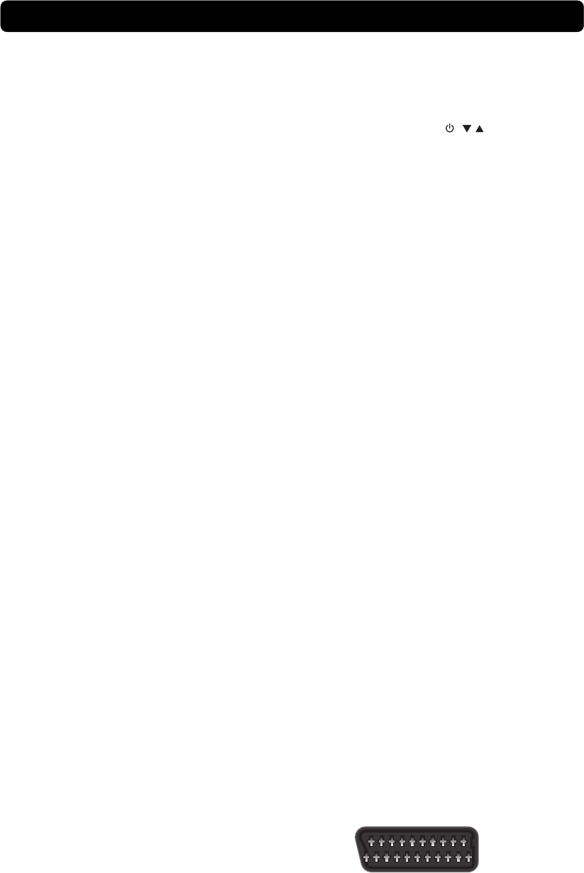
SCART-sockets
TV SAT VIDEO
1 Audio out right ch. - Audio out right ch.
2 - Audio in right ch. Audio in right ch.
3 Audio out left ch. - Audio out left ch.
4 Audio ground Audio ground Audio ground
5 RGB blue ground RGB blue ground -
6 - Audio in left ch. Audio in left ch.
7 RGB blue signal out RGB blue signal in -
8 Switch voltage out Switch voltage in Switch voltage in
9 RGB green ground RGB green ground -
10 - - -
11 RGB green signal out RGB green signal in -
12 - - -
13 RGB red ground RGB red ground -
14 Fast blank. ground Fast blank. ground -
15 RGB red signal out RGB red signal in -
16 Fast blanking out Fast blanking in -
17 Video out ground - Video out ground
18 - Video in ground Video in ground
19 Video out - Video out
20 - Video in Video in
21 Ground (casing) Ground (casing) Ground (casing)
The EMC Directive 89/336/EEC is applied to this product.
Technical Specifications
121
220