


17
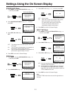
[Please insert video tape.]
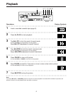
Ô REC, PLAY (1), FF (5), REW (6) or PAUSE
(;) is pressed when no cassette is in the VTR.
Insert a video cassette.
[LOW RF]
Ô Are the video heads dirty?
Clean the video heads using the accessory Digital
Video Head Cleaner.
Before Requesting Service
Before requesting service, check the following points once again.
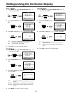
[Recording not allowed. Check setting of the record-
prevention tab.]
Ô Have you pressed REC while using a cassette tape
whose accidental erasure prevention tab has been
set to the SAVE (open) position?
Use a cassette tape whose accidental erasure
prevention tab is set to the REC (closed) position.
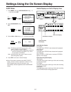
VTR does not operate correctly
The symptom description is indicated in quotations “ ”.
“VTR display is not illuminated.”
Ô Press the power switch. No displays will appear while
the power is off.
Ô Power cord is not connected. Reconnect power cord
to VTR.
“VTR picture does not appear on monitor screen.”
Ô The connections are incorrect.
Check the connections with the monitor.
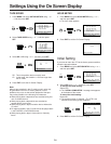
Playback does not operate correctly
The symptom description is indicated in quotations “ ”.
“The playback picture contains rectangular blocks of picture
noise or the whole screen becomes black.”
Ô Video heads are clogged or worn. Use the Digital
Video Head Cleaner supplied with the VTR. (See
page 18.) If the picture is still not clear after using it,
consult your dealer for further advice.
Recording does not operate correctly
The symptom description is indicated in quotations “ ”.
“1 indication flashes whenever recording is attempted.”
Ô The record prevention tab on the cassette is open.
Close the record prevention tab. (Slide it in the
direction of the [REC] arrow.)
“Recordings cannot be made.”
Ô Does INPUT SELECT setting match the sockets that
are actually connected?
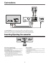
Ô The connections are incorrect. Check that
connections for external video and audio source are
correct. See page 8.
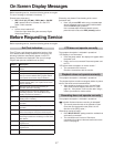
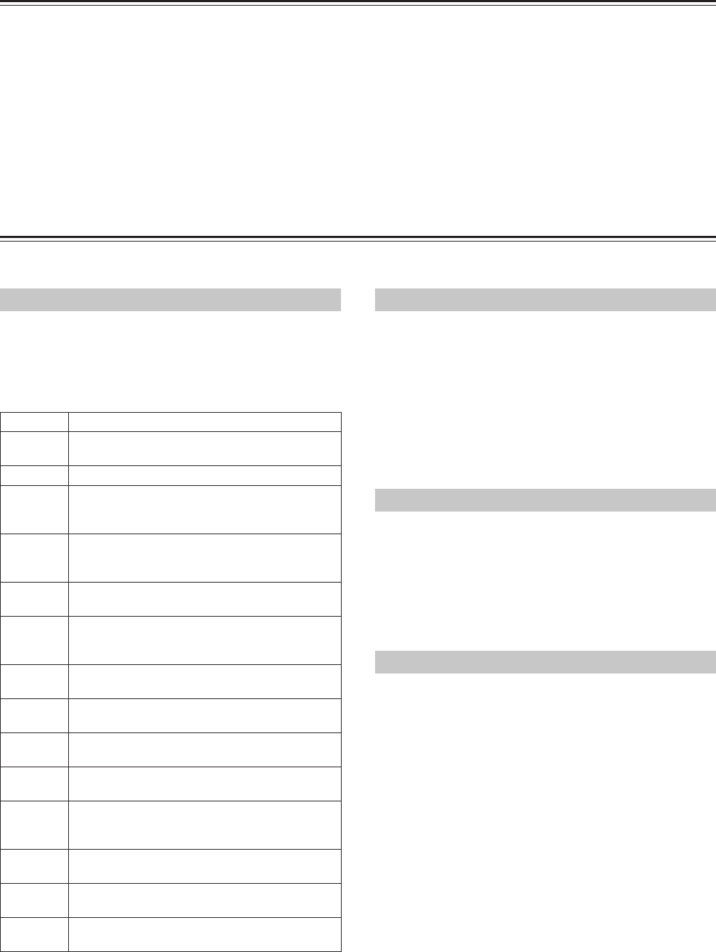
On Screen Display Messages
Before requesting service, check the following points once again.
The error message is indicated in brackets [ ].
Display
U10
U11
H01
H02
F03
F04
F05
F06
F07
F09
F14
H17
H18
H19
Description
Condensation has formed. Wait until this display
clears.
The video heads are dirty. Clean them.
The cylinder does not start up properly or cylinder
lock-up has been detected during regular rotation.
(The cylinder and/or driver may be defective.)
CAP FG is not activated at the down position
(EJECT through REV). (The capstan and/or driver
may be defective.)
Mechanical lock-up has occurred during an
operation other than unloading.
Loading motor has locked up during the tape
unloading operation. (The mode switch or tape
loading mechanism is defective.)
Something is wrong with the reel FG input during
loading and/or unloading.
Slot motor has locked up during the slot IN
operation.
Slot motor has locked up during the slot OUT
operation.
Communication is no longer possible between the
timer microcomputer and syscon microcomputer.
Down position has been detected while operation
was being transferred to unloading in a mode other
than EJECT.
Supply reel lock-up has been detected during
regular travel.
Take-up reel lock-up has been detected during
regular travel.
Fan motor fails to work when the power is turned
on.
Self Test Indication
This VTR has a self-diagnosis and display function. If the
VTR detects trouble during installation or during use, the
following indications automatically appear in the VTR
display. Indications are displayed in the form of a single
English letter plus two numbers such as [H01].